| Author |
Message |
|
|
| |
Post subject: |
Re: SS Hydrograaf, 1/100 3D, hydrographic ship, Royal Dutch |
 |
|
DrPR wrote: Do we have a "technical section? "
Maybe we need a thread for blueprint reading or ship design. I started a separate thread for 3D printing to try to get folks to post information there.
I have repeated this discussion about blueprint reading, Table of Offsets, and other technical points several times in as many threads.
Phil There is a section 'History & Technology': http://www.shipmodels.info/mws_forum/viewforum.php?f=14You need to scroll down on the Board index to find it. As you won't see it right away, I think many people will never look there though... Maybe we shoud adress this to one of the moderators? Otherwise we will repeat ourselves very often, just as you say... [quote="DrPR"]Do we have a "technical section? "
Maybe we need a thread for blueprint reading or ship design. I started a separate thread for 3D printing to try to get folks to post information there.
I have repeated this discussion about blueprint reading, Table of Offsets, and other technical points several times in as many threads.
Phil[/quote]
There is a section 'History & Technology': [url]http://www.shipmodels.info/mws_forum/viewforum.php?f=14[/url]
You need to scroll down on the Board index to find it. As you won't see it right away, I think many people will never look there though... Maybe we shoud adress this to one of the moderators? Otherwise we will repeat ourselves very often, just as you say...
|
|
|
 |
Posted: Tue May 17, 2022 1:01 am |
|
|
 |
|
|
| |
Post subject: |
Re: SS Hydrograaf, 1/100 3D, hydrographic ship, Royal Dutch |
|
|
|
Do we have a "technical section? "
Maybe we need a thread for blueprint reading or ship design. I started a separate thread for 3D printing to try to get folks to post information there.
I have repeated this discussion about blueprint reading, Table of Offsets, and other technical points several times in as many threads.
Phil
|
|
|
|
Posted: Tue May 17, 2022 12:11 am |
|
|
|
|
|
| |
Post subject: |
Re: SS Hydrograaf, 1/100 3D, hydrographic ship, Royal Dutch |
|
|
DrPR wrote: Maarten,
Good points. I was thinking only of ships with a keel angle of zero, even though I am also working on a Baltimore clipper model that has a deeper draft at the stern than at the bow!
However, in plans for those wooden ships sometimes the waterlines are drawn parallel to the load water line and sometimes they are parallel to the keel even though the vessels had greater draft at the stern. In this latter case the frame/station lines in the drawings are perpendicular to the keel, and this complicates matters when trying to use them to create framing for a model!
There is another thing I forgot to mention. The vertical distances are given from a Base Line. There was no specific location for this base line for all vessel construction.
In the case of the Cleveland class cruisers (and presumably other US Navy ships of the mid 20th century) the base line was on top of some of the keel plating. You have to add the keel plating thickness to the vertical dimensions to get the actual height above the bottom of the keel. But I have seen other drawings where the Base Line was the bottom of the keel surface, or the surface of the ways where the vessel was built.
And some small boats hulls are built upside down with the Base Line at some arbitrary position that is above the hull when it is sitting upright.
So you can't take it for granted that the Base Line is where you think it "should" be! Hi DrPR, A Baltimore clipper is even more extreme regarding the keel angle!  up to 20 degrees or so. As for the Zero of the vertical measurements: indeed these vary, and one has to study the plans of the ship in case closely. Adding to the options: some designers use the (theoretical) Load Waterline as the origin, al the measuremenst downwards are negative, upwards positive. So I go with your conclusion: don't take it for granted but study the information you've got closely before you dive into building something! Just to give a warning: as for the longitudinal measurements you must be aware the Zero point might also be chosen arbitrarily. Most designers place this at either the Forward or the Aft Perpendicular -- the ends where the ship's stem and stern cross the waterline, but there are variations with the definition of these too. In many cases the rudder axis is used as the Aft perpendicular for instance. One more note: should we not take this discussion off the Hydrograaf topic and start a separate discussion on ship design in the technical section? [quote="DrPR"]Maarten,
Good points. I was thinking only of ships with a keel angle of zero, even though I am also working on a Baltimore clipper model that has a deeper draft at the stern than at the bow!
However, in plans for those wooden ships sometimes the waterlines are drawn parallel to the load water line and sometimes they are parallel to the keel even though the vessels had greater draft at the stern. In this latter case the frame/station lines in the drawings are perpendicular to the keel, and this complicates matters when trying to use them to create framing for a model!
There is another thing I forgot to mention. The vertical distances are given from a Base Line. There was no specific location for this base line for all vessel construction.
In the case of the Cleveland class cruisers (and presumably other US Navy ships of the mid 20th century) the base line was on top of some of the keel plating. You have to add the keel plating thickness to the vertical dimensions to get the actual height above the bottom of the keel. But I have seen other drawings where the Base Line was the bottom of the keel surface, or the surface of the ways where the vessel was built.
And some small boats hulls are built upside down with the Base Line at some arbitrary position that is above the hull when it is sitting upright.
So you can't take it for granted that the Base Line is where you think it "should" be![/quote]
Hi DrPR,
A Baltimore clipper is even more extreme regarding the keel angle! :big_grin: up to 20 degrees or so.
As for the Zero of the vertical measurements: indeed these vary, and one has to study the plans of the ship in case closely. Adding to the options: some designers use the (theoretical) Load Waterline as the origin, al the measuremenst downwards are negative, upwards positive. So I go with your conclusion: don't take it for granted but study the information you've got closely before you dive into building something!
Just to give a warning: as for the [i]longitudinal [/i]measurements you must be aware the Zero point might also be chosen arbitrarily. Most designers place this at either the Forward or the Aft Perpendicular -- the ends where the ship's stem and stern cross the waterline, but there are variations with the definition of these too. In many cases the rudder axis is used as the Aft perpendicular for instance.
One more note: should we not take this discussion off the Hydrograaf topic and start a separate discussion on ship design in the technical section?
|
|
|
|
Posted: Mon May 16, 2022 1:58 am |
|
|
|
|
|
| |
Post subject: |
Re: SS Hydrograaf, 1/100 3D, hydrographic ship, Royal Dutch |
|
|
|
Maarten,
Good points. I was thinking only of ships with a keel angle of zero, even though I am also working on a Baltimore clipper model that has a deeper draft at the stern than at the bow!
However, in plans for those wooden ships sometimes the waterlines are drawn parallel to the load water line and sometimes they are parallel to the keel even though the vessels had greater draft at the stern. In this latter case the frame/station lines in the drawings are perpendicular to the keel, and this complicates matters when trying to use them to create framing for a model!
There is another thing I forgot to mention. The vertical distances are given from a Base Line. There was no specific location for this base line for all vessel construction.
In the case of the Cleveland class cruisers (and presumably other US Navy ships of the mid 20th century) the base line was on top of some of the keel plating. You have to add the keel plating thickness to the vertical dimensions to get the actual height above the bottom of the keel. But I have seen other drawings where the Base Line was the bottom of the keel surface, or the surface of the ways where the vessel was built.
And some small boats hulls are built upside down with the Base Line at some arbitrary position that is above the hull when it is sitting upright.
So you can't take it for granted that the Base Line is where you think it "should" be!
|
|
|
|
Posted: Mon May 16, 2022 12:31 am |
|
|
|
|
|
| |
Post subject: |
Re: SS Hydrograaf, 1/100 3D, hydrographic ship, Royal Dutch |
|
|
DrPR wrote: Horizontal cross sections of the hull at vertical distances (the Y coordinate) were called waterlines. There were as many waterlines as you wanted to draw. Imagine a ship in an empty dry dock. Then as water flows in and reaches a level a foot above the bottom of the keel where the water surface meets the hull is the one foot waterline. When the water level is two feet above the keel it is the two foot waterline, etc. The light load waterline, normal load waterline and full load waterlines are special depths that are used for ship loading. Very good summary of the ship's anatomy measuring system! I have one important addition to make here: waterlines are always parallel to the design waterline of the ship. That is not necessarily parallel to the keel! Until about 1900 (sailing)ships always had their rear of the keel deeper into the water than the forefoot, for getting sufficient water pressure on the rudder. With tugs and fishing boats this is still always the case, now also to have the props as deep into the water as to give good rendement. In those cases the angle between the keel and the waterline(s) can be up to 10 degrees, sometimes even more. So the example DrPR gave is only true for a ship with this angle being 0, which is today the case for most cargo and passenger ships, most naval ships too. But you must ascertain this for every design you make. And another remark: ususally the forward-backward axis we call X (stations/frames), the lateral left-right axis Y (butt lines) and the vertical axis Z (waterlines). But of course that may be arbitrary. [quote="DrPR"]Horizontal cross sections of the hull at vertical distances (the Y coordinate) were called waterlines. There were as many waterlines as you wanted to draw. Imagine a ship in an empty dry dock. Then as water flows in and reaches a level a foot above the bottom of the keel where the water surface meets the hull is the one foot waterline. When the water level is two feet above the keel it is the two foot waterline, etc. The light load waterline, normal load waterline and full load waterlines are special depths that are used for ship loading.[/quote]
Very good summary of the ship's anatomy measuring system!
I have one important addition to make here: waterlines are always parallel to the [u]design waterline[/u] of the ship. That is not necessarily parallel to the keel!
Until about 1900 (sailing)ships always had their rear of the keel deeper into the water than the forefoot, for getting sufficient water pressure on the rudder. With tugs and fishing boats this is still always the case, now also to have the props as deep into the water as to give good rendement. In those cases the angle between the keel and the waterline(s) can be up to 10 degrees, sometimes even more.
So the example DrPR gave is only true for a ship with this angle being 0, which is today the case for most cargo and passenger ships, most naval ships too. But you must ascertain this for every design you make.
And another remark: ususally the forward-backward axis we call X (stations/frames), the lateral left-right axis Y (butt lines) and the vertical axis Z (waterlines). But of course that may be arbitrary.
|
|
|
|
Posted: Sun May 15, 2022 10:36 am |
|
|
|
|
|
| |
Post subject: |
Re: SS Hydrograaf, 1/100 3D, hydrographic ship, Royal Dutch |
|
|
That's an awesome bit of knowledge - thank you for sharing. Will be on the lookout for those tables of offsets. However, I feel like we are moving further and further away from Pascal's topic and I don't want take away from his awesome work, so I started a new topic where we can discuss 3d modelling ship hulls here and we can leave this topic to discussing his amazing SS Hydrograaf model  That's an awesome bit of knowledge - thank you for sharing. Will be on the lookout for those tables of offsets.
However, I feel like we are moving further and further away from Pascal's topic and I don't want take away from his awesome work, so I started a new topic where we can discuss 3d modelling ship hulls [url=http://www.shipmodels.info/mws_forum/viewtopic.php?f=27&t=354804]here[/url] and we can leave this topic to discussing his amazing SS Hydrograaf model :)
|
|
|
|
Posted: Sun May 15, 2022 9:31 am |
|
|
|
|
|
| |
Post subject: |
Re: SS Hydrograaf, 1/100 3D, hydrographic ship, Royal Dutch |
|
|
|
There is a way to create hull lines in CAD programs (if your program supports it) that produces very accurate lines. Many blueprints have a "Table of Offsets." These offsets are XYZ coordinates for points on the hull surface (actually these "molded" offsets are usually to the inside of the hull plating, for the frames the plating attaches to).
The X coordinate is a position lengthwise (bow to stern) on the hull. The Y coordinate is the vertical dimension from a base line that may or may not be the bottom of the keel. And the Z coordinate is the distance transverse (port to starboard) to the hull center line.
Stations/frames were transverse slices through the hull. The X coordinates are given for stations or frames along the length of the hull. The distance between stations or frames varies with the vessel type, so you need to determine what this distance is. So for X distance station/frame 1 will be X distance from station/frame 0, station 2 will be 2X distant, and so on. Stations/frames are numbered between the Fore Peak and the Aft Peak (or After Peak). The Fore Peak is the point where the foremost part of the hull meets the normal load waterline. The Aft Peak is the aft most point on the hull at the load water line for modern vessels. (However, for wooden sailing ships the Aft Peak was where the center line of the rudder post crossed the load water line) Also, for American ships the station/frame numbering started at the Fore Peak (station/frame 0), but many (all) European countries put station/frame 0 at the Aft Peak.
Horizontal cross sections of the hull at vertical distances (the Y coordinate) were called waterlines. There were as many waterlines as you wanted to draw. Imagine a ship in an empty dry dock. Then as water flows in and reaches a level a foot above the bottom of the keel where the water surface meets the hull is the one foot waterline. When the water level is two feet above the keel it is the two foot waterline, etc. The light load waterline, normal load waterline and full load waterlines are special depths that are used for ship loading.
Vertical slices of the hull along the length of the ship were called butt lines. A slice on foot port/starboard from the center line was the one foot butt line, five feet from the center line was the five foot butt line, etc.
The Table of Offsets will list the Y (waterline) and Z (butt line) distances to points on the hull at each X position (station/frame). All together the Table defines the 3D shape of the hull. Many 3D CAD programs will import XYZ coordinate files and automatically generate the hull lines. This is far more accurate that trying to scan small scale line drawings.
The catch is that you have to create the plain text XYZ coordinate files in the format the program wants. Furthermore, the values in the Table of Offsets (American) are given in numbers like 12-9-3, which is 12 feet, nine and 3/8 inch, which is 12.78125 feet. So entering hundreds of these numbers into a spreadsheet is a bit tedious! But once you have the XYZ coordinate file you can regenerate the accurate hull shape in the CAD program as many times as you want.
Phil
There is a way to create hull lines in CAD programs (if your program supports it) that produces very accurate lines. Many blueprints have a "Table of Offsets." These offsets are XYZ coordinates for points on the hull surface (actually these "molded" offsets are usually to the [i]inside[/i] of the hull plating, for the frames the plating attaches to).
The X coordinate is a position lengthwise (bow to stern) on the hull. The Y coordinate is the vertical dimension from a base line that may or may not be the bottom of the keel. And the Z coordinate is the distance transverse (port to starboard) to the hull center line.
Stations/frames were transverse slices through the hull. The X coordinates are given for stations or frames along the length of the hull. The distance between stations or frames varies with the vessel type, so you need to determine what this distance is. So for X distance station/frame 1 will be X distance from station/frame 0, station 2 will be 2X distant, and so on. Stations/frames are numbered between the Fore Peak and the Aft Peak (or After Peak). The Fore Peak is the point where the foremost part of the hull meets the normal load waterline. The Aft Peak is the aft most point on the hull at the load water line for modern vessels. (However, for wooden sailing ships the Aft Peak was where the center line of the rudder post crossed the load water line) Also, for American ships the station/frame numbering started at the Fore Peak (station/frame 0), but many (all) European countries put station/frame 0 at the Aft Peak.
Horizontal cross sections of the hull at vertical distances (the Y coordinate) were called waterlines. There were as many waterlines as you wanted to draw. Imagine a ship in an empty dry dock. Then as water flows in and reaches a level a foot above the bottom of the keel where the water surface meets the hull is the one foot waterline. When the water level is two feet above the keel it is the two foot waterline, etc. The light load waterline, normal load waterline and full load waterlines are special depths that are used for ship loading.
Vertical slices of the hull along the length of the ship were called butt lines. A slice on foot port/starboard from the center line was the one foot butt line, five feet from the center line was the five foot butt line, etc.
The Table of Offsets will list the Y (waterline) and Z (butt line) distances to points on the hull at each X position (station/frame). All together the Table defines the 3D shape of the hull. Many 3D CAD programs will import XYZ coordinate files and automatically generate the hull lines. This is far more accurate that trying to scan small scale line drawings.
The catch is that you have to create the plain text XYZ coordinate files in the format the program wants. Furthermore, the values in the Table of Offsets (American) are given in numbers like 12-9-3, which is 12 feet, nine and 3/8 inch, which is 12.78125 feet. So entering hundreds of these numbers into a spreadsheet is a bit tedious! But once you have the XYZ coordinate file you can regenerate the accurate hull shape in the CAD program as many times as you want.
Phil
|
|
|
|
Posted: Sun May 15, 2022 12:32 am |
|
|
|
|
|
| |
Post subject: |
Re: SS Hydrograaf, 1/100 3D, hydrographic ship, Royal Dutch |
|
|
Thanks both for the feedback! While I'm less excited about creating hulls for simple boats, you're both right that I should go with it for my first try. Once I've progressed more on my current project, I will look into plans of something like a viking boat. I also had another idea of using scans of old paper models (those were quite popular in Poland, where I'm originally from) and recreate the "skeleton" of the hull (which is basically vertical cuts of the hull) and build the hull curves based on those... but, while this shortcut would let me make some complex hulls *now* it wouldn't really teach me what I really want to do  Nonetheless, I found few models of Polish ships I might recreate that way in the future Thanks both for the feedback!
While I'm less excited about creating hulls for simple boats, you're both right that I should go with it for my first try. Once I've progressed more on my current project, I will look into plans of something like a viking boat.
I also had another idea of using scans of old paper models (those were quite popular in Poland, where I'm originally from) and recreate the "skeleton" of the hull (which is basically vertical cuts of the hull) and build the hull curves based on those... but, while this shortcut would let me make some complex hulls *now* it wouldn't really teach me what I really want to do :P Nonetheless, I found few models of Polish ships I might recreate that way in the future :)
|
|
|
|
Posted: Sat May 14, 2022 12:54 pm |
|
|
|
|
|
| |
Post subject: |
Re: SS Hydrograaf, 1/100 3D, hydrographic ship, Royal Dutch |
|
|
|
vb,
Small hulls are not necessarily easier to model in CAD than large hulls. I found that modeling a 28 foot motor launch was about as challenging as the hull as a 610 foot cruiser.
Smooth hulls like canoes are pretty easy. But some hulls have irregularities like skegs (where the keel ends forward of the stern) or knuckles (sharp edges between smooth curves). The smoothly curved parts are easy to model. It is the irregularities than can cause you to pull your hair out!
Like Maarten said, a clinker hull is far harder to model than a smooth hull. And if you plan to model the hull plating you can count on a lot more work (and frustration).
However, after you have modeled your first complex hull you will have the satisfaction of knowing that you have accomplished something!
Phil
|
|
|
|
Posted: Fri May 13, 2022 12:32 am |
|
|
|
|
|
| |
Post subject: |
Re: SS Hydrograaf, 1/100 3D, hydrographic ship, Royal Dutch |
|
|
von_bednar wrote: Thank you both!
It seems I have been approaching it the wrong way - my thinking was: find an archive, look through what's available and choose something close to what I'm looking for. Seems I have some researching to do first to try to find ship name and/or model of what I'm after.
I think my first proper attempt of modelling a hull should be something smaller (just because my assumption that smaller vessel = simpler) and I was thinking of a tugboat to go with the steamer I'm currently working on (and also because modelling a lifeboat or rowboat, while definitely simpler, does not seem as exciting) . Will look into early XX century tugs and see what I can find. Is there a good place where I could start my research?  You might be surprised how complex the hull of a tugboat is! To be honest, any ship's hull is a complex shape to model in 3D - but then, I have no real 3D experience. To me, a viking ship with stem and stern being the same would probably the simplest form, but as soon as you add the clinker hull planks it's becoming complicated already. A hull like the 'Hydrograaf' in itself is not very complex (better ask Iceman 29) but then the hull plating and the stern with rudder make it complex again. Yo'll find soon enough when you start. But any generic or diesel steam cargo ship is probably a good starting point. [quote="von_bednar"]Thank you both!
It seems I have been approaching it the wrong way - my thinking was: find an archive, look through what's available and choose something close to what I'm looking for. Seems I have some researching to do first to try to find ship name and/or model of what I'm after.
I think my first proper attempt of modelling a hull should be something smaller (just because my assumption that smaller vessel = simpler) and I was thinking of a tugboat to go with the steamer I'm currently working on (and also because modelling a lifeboat or rowboat, while definitely simpler, does not seem as exciting) . Will look into early XX century tugs and see what I can find. Is there a good place where I could start my research?[/quote]
:smallsmile: You might be surprised how complex the hull of a tugboat is! To be honest, any ship's hull is a complex shape to model in 3D - but then, I have no real 3D experience. To me, a viking ship with stem and stern being the same would probably the simplest form, but as soon as you add the clinker hull planks it's becoming complicated already.
A hull like the 'Hydrograaf' in itself is not very complex (better ask Iceman 29) but then the hull plating and the stern with rudder make it complex again. Yo'll find soon enough when you start. But any generic or diesel steam cargo ship is probably a good starting point.
|
|
|
|
Posted: Thu May 12, 2022 2:33 pm |
|
|
|
|
|
| |
Post subject: |
Re: SS Hydrograaf, 1/100 3D, hydrographic ship, Royal Dutch |
|
|
|
Thank you both!
It seems I have been approaching it the wrong way - my thinking was: find an archive, look through what's available and choose something close to what I'm looking for. Seems I have some researching to do first to try to find ship name and/or model of what I'm after.
I think my first proper attempt of modelling a hull should be something smaller (just because my assumption that smaller vessel = simpler) and I was thinking of a tugboat to go with the steamer I'm currently working on (and also because modelling a lifeboat or rowboat, while definitely simpler, does not seem as exciting) . Will look into early XX century tugs and see what I can find. Is there a good place where I could start my research?
|
|
|
|
Posted: Thu May 12, 2022 7:33 am |
|
|
|
|
|
| |
Post subject: |
Re: SS Hydrograaf, 1/100 3D, hydrographic ship, Royal Dutch |
|
|
Maarten Schönfeld wrote: So the question is: which particular ship do you want to model? If you can name it, then there are people here on the forum that might help finding the required plans. That is the best advice. For some states, there are central archives, but even those usually contain not all ships, but for some of them other archives have the plans. General statements are therefore difficult. For Germany, I know probably 20 or more archives to contact depending on the ship. [quote="Maarten Schönfeld"]So the question is: which particular ship do you want to model? If you can name it, then there are people here on the forum that might help finding the required plans.[/quote]
That is the best advice. For some states, there are central archives, but even those usually contain not all ships, but for some of them other archives have the plans. General statements are therefore difficult. For Germany, I know probably 20 or more archives to contact depending on the ship.
|
|
|
|
Posted: Thu May 12, 2022 3:52 am |
|
|
|
|
|
| |
Post subject: |
Re: SS Hydrograaf, 1/100 3D, hydrographic ship, Royal Dutch |
|
|
von_bednar wrote: As for questions, I think I will start at the beginning: where would I begin to look for good ship blueprints/plans? So far I only found one website hosting a few, but from reading through your topics it seems you are able to find really detailed plans. I feel if I were to model myself a ship from scratch (currently using a pre-made hull) I would really need those. May I take this one up? For the 'Hydrograaf' the plans can be found in the Dutch National Archives in The Hague, these are all online available for free, here's the link: https://www.nationaalarchief.nl/onderzoeken/archief/4.MST/invnr/%401~1.2~1.2.28~4324-4340 For the ship's boat's, these can also be found here but these were generic for the Dutch navy and can be found in the small vessel's section. But for other ships: it really depends on the ship in case where you have to look, there are no sites having all ships of the world. But for starters, US Naval ships of the past may be found in the HSNA site, and commercially on the Floating Drydock website. British ships may be found in the Greenwich Maritime Museum archives (expensive!) but some can be found elsewhere too. German ships can be found either commercially or some historical ships on Russian (!) websites. Andsoforth andsofurther. So the question is: which particular ship do you want to model? If you can name it, then there are people here on the forum that might help finding the required plans. [quote="von_bednar"]
As for questions, I think I will start at the beginning: where would I begin to look for good ship blueprints/plans?
So far I only found [url=http://www.shipmodell.com/index_files/0PLAN3B.html]one website hosting a few[/url], but from reading through your topics it seems you are able to find really detailed plans. I feel if I were to model myself a ship from scratch (currently using a pre-made hull) I would really need those.[/quote]
May I take this one up? For the 'Hydrograaf' the plans can be found in the Dutch National Archives in The Hague, these are all online available for free, here's the link: [url]https://www.nationaalarchief.nl/onderzoeken/archief/4.MST/invnr/%401~1.2~1.2.28~4324-4340[/url]
For the ship's boat's, these can also be found here but these were generic for the Dutch navy and can be found in the small vessel's section.
But for other ships: it really depends on the ship in case where you have to look, there are no sites having all ships of the world. But for starters, US Naval ships of the past may be found in the HSNA site, and commercially on the Floating Drydock website. British ships may be found in the Greenwich Maritime Museum archives (expensive!) but some can be found elsewhere too. German ships can be found either commercially or some historical ships on Russian (!) websites. Andsoforth andsofurther.
So the question is: which particular ship do you want to model? If you can name it, then there are people here on the forum that might help finding the required plans.
|
|
|
|
Posted: Thu May 12, 2022 3:34 am |
|
|
|
|
|
| |
Post subject: |
Re: SS Hydrograaf, 1/100 3D, hydrographic ship, Royal Dutch |
|
|
@Pascal: While it saddens me that I won't be able to put together your models, I completely understand your choice not to share them. As for questions, I think I will start at the beginning: where would I begin to look for good ship blueprints/plans? So far I only found one website hosting a few, but from reading through your topics it seems you are able to find really detailed plans. I feel if I were to model myself a ship from scratch (currently using a pre-made hull) I would really need those. Secondly, I was wondering if you could point me to some resources about modelling hulls. I only have hobby experience with Rhino3D and Fusion360, and while I'm capable of modelling things for 3d print, I feel like there's another lever of knowledge when it comes to modeling complex curvilinear shapes like hulls. @Neptune Thank you for letting me know. For time being I will lurk around and read the forums and ask questions in open topics when applicable. Definitely don't want to be 'that guy' who goes around and sends unsolicited private messages to people  @Pascal:
While it saddens me that I won't be able to put together your models, I completely understand your choice not to share them.
As for questions, I think I will start at the beginning: where would I begin to look for good ship blueprints/plans?
So far I only found [url=http://www.shipmodell.com/index_files/0PLAN3B.html]one website hosting a few[/url], but from reading through your topics it seems you are able to find really detailed plans. I feel if I were to model myself a ship from scratch (currently using a pre-made hull) I would really need those.
Secondly, I was wondering if you could point me to some resources about modelling hulls. I only have hobby experience with Rhino3D and Fusion360, and while I'm capable of modelling things for 3d print, I feel like there's another lever of knowledge when it comes to modeling complex curvilinear shapes like hulls.
@Neptune
Thank you for letting me know. For time being I will lurk around and read the forums and ask questions in open topics when applicable. Definitely don't want to be 'that guy' who goes around and sends unsolicited private messages to people ;)
|
|
|
|
Posted: Wed May 11, 2022 8:14 pm |
|
|
|
|
|
| |
Post subject: |
Re: SS Hydrograaf, 1/100 3D, hydrographic ship, Royal Dutch |
|
|
|
If I remember correctly, you should be able to send personal messages after making 3 or 5 posts on the forum itself.
If I remember correctly, you should be able to send personal messages after making 3 or 5 posts on the forum itself.
|
|
|
|
Posted: Tue May 10, 2022 5:55 am |
|
|
|
|
|
| |
Post subject: |
Re: SS Hydrograaf, 1/100 3D, hydrographic ship, Royal Dutch |
|
|
Thank you very much, Fred.  1 - No, I never sell my print files, sorry. 2 - You can ask your questions here, no worries. Thank you very much, Fred. :thumbs_up_1:
1 - No, I never sell my print files, sorry.
2 - You can ask your questions here, no worries.
|
|
|
|
Posted: Sun May 08, 2022 3:02 pm |
|
|
|
|
|
| |
Post subject: |
Re: SS Hydrograaf, 1/100 3D, hydrographic ship, Royal Dutch |
|
|
Oh wow! This built made me join this forum. I stumbled upon it today when looking for example deck layouts of tram steamers as I'm trying to get into model making and I'm currently working on trying to 3d model my own tramp steamer based on some simplified model I found, so I can 3d print it later. Needless to say your build puts my efforts to shame  It is truly amazing! I want to ask so many questions, but don't think it would be suitable to ask on the forum, and it doesn't seem like I can send private messages on here. So I will limit myself to only two: 1. Are your models available anywhere so others could print them themselves? 2. Could I contact you over email (or you can send a private message on here if you can) to be able to ask more questions? -- Fred. Oh wow!
This built made me join this forum. I stumbled upon it today when looking for example deck layouts of tram steamers as I'm trying to get into model making and I'm currently working on trying to 3d model my own tramp steamer based on some simplified model I found, so I can 3d print it later.
Needless to say your build puts my efforts to shame :D It is truly amazing!
I want to ask so many questions, but don't think it would be suitable to ask on the forum, and it doesn't seem like I can send private messages on here. So I will limit myself to only two:
1. Are your models available anywhere so others could print them themselves?
2. Could I contact you over email (or you can send a private message on here if you can) to be able to ask more questions?
--
Fred.
|
|
|
|
Posted: Mon May 02, 2022 11:52 pm |
|
|
|
|
|
| |
Post subject: |
Re: SS Hydrograaf, 1/100 3D, hydrographic ship, Royal Dutch |
|
|
Maarten Schönfeld wrote: Hi Pascal, For some reason I missed the final stages of your build, the end result is beautiful! My full congratulations. Maarten Glad to read you. Thank you Maarten for your documentary help, wise advice and encouragement throughout this project. [quote="Maarten Schönfeld"]Hi Pascal,
For some reason I missed the final stages of your build, the end result is beautiful! My full congratulations. :thumbs_up_1: :smallsmile:
Maarten[/quote]
Glad to read you.
Thank you Maarten for your documentary help, wise advice and encouragement throughout this project. :thumbs_up_1:
|
|
|
|
Posted: Sat Jan 15, 2022 8:22 am |
|
|
|
|
|
| |
Post subject: |
Re: SS Hydrograaf, 1/100 3D, hydrographic ship, Royal Dutch |
|
|
Hi Pascal, For some reason I missed the final stages of your build, the end result is beautiful! My full congratulations. Maarten Hi Pascal,
For some reason I missed the final stages of your build, the end result is beautiful! My full congratulations. :thumbs_up_1: :smallsmile:
Maarten
|
|
|
|
Posted: Sat Jan 15, 2022 7:41 am |
|
|
|
|
|
| |
Post subject: |
Re: SS Hydrograaf, 1/100 3D, hydrographic ship, Royal Dutch |
|
|
|
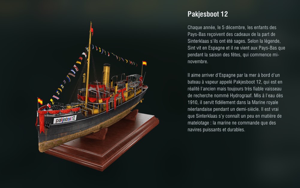
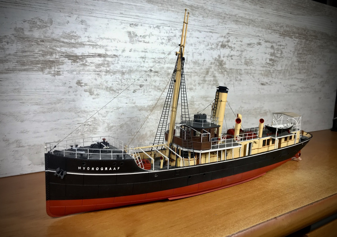
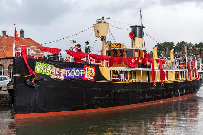
Seen on World Of Warships (well known online game) last Christmas by a friend, thanks to him for the screenshots.
Surprising, isn't it? From there to think that they were inspired...
[img]https://i.servimg.com/u/f87/19/56/38/79/captur10.jpg[/img]
[img]https://i.servimg.com/u/f87/19/56/38/79/captur11.jpg[/img]
[img]https://i.postimg.cc/MHGZrLNF/Screenshot-2021-12-05-22-37-30-741.jpg[/img]
[img]https://images0.persgroep.net/rcs/OBSRi95otXilu9TT2c1lST0GR-U/diocontent/135202674/_fitwidth/694/?appId=21791a8992982cd8da851550a453bd7f&quality=0.8&desiredformat=webp[/img]
|
|
|
|
Posted: Wed Jan 12, 2022 4:05 pm |
|
|
|
|