| Author |
Message |
|
|
| |
Post subject: |
Re: 1/400 MN Béarn |
 |
|
Thanks, Martin! Some more changes follow in this update. I noticed the added foil was loose at the edges. To ensure it to properly adhere to the plastic, I clamped a metal object to it and poured some Zap under the edge.  The starboard edge where the island sits, slightly deviates to the bow. This is according to plans, but the hull doesn't fit to the deck like that. Also, if the island is aligned to that, the stack would not be parallel to the keel.  So I cut it along the hull line and rounded the rear part again.  The tie-down-like things and other removed deck parts were added again. I made the planking foil to tight and I had to add a metal strip to both sides. Some filing was needed to level that strip.  Before fixing the deck, I made sure stuff can't fall in the elevators and disappear. I walled off the open holes with some leftover foil parts that were painted grey, I know there were fire curtains in the hangar. Then the main part of the deck was glued to the hull with some clamping.  The extremities are fixed later on with superfluous styrene glue. The deck was too stubborn to risk CA glue.  The 1935 changes to the ship were not all provided in the kit, so I had to make an important addition to the front deck edge.  In this 1936 picture the changes under the flight deck can be seen.  First the bracing under the girders had to be sawn off. This risky undertaking was almost done when the entire girder was knocked away. It was put back where it belongs and the stumps were filed.   Drilling the holes in the plating could be done with the Proxxon, but I hate to clamp the parts. I could manage it with the Dremel.  The 5 plates were then glued between the posts. There was a working space inside. I don't know if I can add a floor between them, there is a telescopic mast going through.   Thanks, Martin! Some more changes follow in this update.
I noticed the added foil was loose at the edges. To ensure it to properly adhere to the plastic, I clamped a metal object to it and poured some Zap under the edge.
[img]https://www.modelbrouwers.nl/media/cache/5f/15/5f15780d3246c9ddae172fc42f7a097e.jpg[/img]
The starboard edge where the island sits, slightly deviates to the bow. This is according to plans, but the hull doesn't fit to the deck like that. Also, if the island is aligned to that, the stack would not be parallel to the keel.
[img]https://www.modelbrouwers.nl/media/cache/a2/c9/a2c9af183d8c088cf2c4965a17e6871f.jpg[/img]
So I cut it along the hull line and rounded the rear part again.
[img]https://www.modelbrouwers.nl/media/cache/cf/fa/cffae3a24147bccb5fd71d83e539d1ae.jpg[/img]
The tie-down-like things and other removed deck parts were added again. I made the planking foil to tight and I had to add a metal strip to both sides. Some filing was needed to level that strip.
[img]https://www.modelbrouwers.nl/media/cache/98/2a/982a300851757fe3e0a75cbfd55fdc35.jpg[/img]
Before fixing the deck, I made sure stuff can't fall in the elevators and disappear. I walled off the open holes with some leftover foil parts that were painted grey, I know there were fire curtains in the hangar. Then the main part of the deck was glued to the hull with some clamping.
[img]https://www.modelbrouwers.nl/media/cache/34/1b/341b5c894b899c9009650e9a287acece.jpg[/img]
The extremities are fixed later on with superfluous styrene glue. The deck was too stubborn to risk CA glue.
[img]https://www.modelbrouwers.nl/media/cache/00/d8/00d810788a894c01169efb8a46073a68.jpg[/img]
The 1935 changes to the ship were not all provided in the kit, so I had to make an important addition to the front deck edge.
[img]https://www.modelbrouwers.nl/media/cache/c7/33/c733351138d3eaa2dc315c56e7e136f4.jpg[/img]
In this 1936 picture the changes under the flight deck can be seen.
[img]https://www.modelbrouwers.nl/media/cache/8e/a3/8ea333c6f40d3ed4e74f95193e502d6d.jpg[/img]
First the bracing under the girders had to be sawn off. This risky undertaking was almost done when the entire girder was knocked away. It was put back where it belongs and the stumps were filed.
[img]https://www.modelbrouwers.nl/media/cache/f5/4e/f54efc05960fec092efe41d8de8512c5.jpg[/img]
[img]https://www.modelbrouwers.nl/media/cache/98/66/9866178c74eef1b498d87d5ed8e4587b.jpg[/img]
Drilling the holes in the plating could be done with the Proxxon, but I hate to clamp the parts. I could manage it with the Dremel.
[img]https://www.modelbrouwers.nl/media/cache/ab/99/ab997462203d7133c2415a996b4d249e.jpg[/img]
The 5 plates were then glued between the posts. There was a working space inside. I don't know if I can add a floor between them, there is a telescopic mast going through.
[img]https://www.modelbrouwers.nl/media/cache/3a/35/3a3552a2cc07ec61b5512a708f9e24b6.jpg[/img]
[img]https://www.modelbrouwers.nl/media/cache/7d/be/7dbe77f93ce25d734d382a62096316ac.jpg[/img]
|
|
|
 |
Posted: Tue Jul 15, 2025 6:02 am |
|
|
 |
|
|
| |
Post subject: |
Re: 1/400 MN Béarn |
|
|
|
Wow! You are ALL in on this build! Very creative solutions
Wow! You are ALL in on this build! Very creative solutions
|
|
|
|
Posted: Sat Jul 12, 2025 9:06 am |
|
|
|
|
|
| |
Post subject: |
Re: 1/400 MN Béarn |
|
|
Now it was time to tackle the planking.  I had toyed with the idea to disassemble the unused Dunkerque decks that are in my stash. After counting the planks on one half beam section I got to 100. If the beam of 6.3 mm was divided by 200, a plank width of 0.3mm resulted. Even the generic decks for 1/700 on Scalemates only go to 0.5mm. Wood decks were apparently out of the question.  But there is a way to get to this using metal foil, like I did on earlier BB builds. A series of points at 3mm interval is connected with an engraved line, and then these are separated in 3 strips, and the last step is to try to get two lines in each of these 1mm strips. Not all of these were on par, but the general idea looks like it should. No butt ends were attempted, these look irregular in pattern.  Drawing these lines and paying equal attention to each offset is the hard part.  Two parts are needed, the flight deck length exceeds the metail foil dimension.  While trimming I missed the rear elevator edge. This means there is a seam close to that edge.  The elevator shaft is opened up. I am happy there are no rounds like on US carriers.   After removing some deck edge details, the new surface can be applied on the rear deck and the elevator doors.  The front part has a system of what look like tie-downs. This is copied to the metal deck.  The cutting of this copy causes some canning.  That can be hammered out.  The front deck part is also fixed with CA and the seam is filled. The only thing missing is the deck edge plank running around the flight deck. On the rounded parts this will be evident, but if I would remove 1 mm I would need a plank that can be molded around the deck edge. Maybe I should avoid this like I avoid the butt ends... Now it was time to tackle the planking.
[img]https://www.modelbrouwers.nl/media/cache/43/fb/43fbc9a0ee1226fc8a1959f880e9385c.jpg[/img]
I had toyed with the idea to disassemble the unused Dunkerque decks that are in my stash. After counting the planks on one half beam section I got to 100. If the beam of 6.3 mm was divided by 200, a plank width of 0.3mm resulted. Even the generic decks for 1/700 on Scalemates only go to 0.5mm. Wood decks were apparently out of the question.
[img]https://www.modelbrouwers.nl/media/cache/1a/e0/1ae042485a9d57915a47b82f8d447685.jpg[/img]
But there is a way to get to this using metal foil, like I did on earlier BB builds. A series of points at 3mm interval is connected with an engraved line, and then these are separated in 3 strips, and the last step is to try to get two lines in each of these 1mm strips. Not all of these were on par, but the general idea looks like it should. No butt ends were attempted, these look irregular in pattern.
[img]https://www.modelbrouwers.nl/media/cache/de/84/de84b01691c6750b0be44a46957559d6.jpg[/img]
Drawing these lines and paying equal attention to each offset is the hard part.
[img]https://www.modelbrouwers.nl/media/cache/b4/20/b4207782b2c5f55a279728814391b19b.jpg[/img]
Two parts are needed, the flight deck length exceeds the metail foil dimension.
[img]https://www.modelbrouwers.nl/media/cache/66/fb/66fb9df033a257618f8d405a032b9748.jpg[/img]
While trimming I missed the rear elevator edge. This means there is a seam close to that edge.
[img]https://www.modelbrouwers.nl/media/cache/37/1e/371e1e225d610b23c08777cddf053048.jpg[/img]
The elevator shaft is opened up. I am happy there are no rounds like on US carriers.
[img]https://www.modelbrouwers.nl/media/cache/27/71/27715729d05517b03c1523ef1ac007e9.jpg[/img]
[img]https://www.modelbrouwers.nl/media/cache/0a/ce/0ace6aeabc5d430a701f6f6490e53a92.jpg[/img]
After removing some deck edge details, the new surface can be applied on the rear deck and the elevator doors.
[img]https://www.modelbrouwers.nl/media/cache/ce/01/ce01d2d95678bbdb689bad627c94d566.jpg[/img]
The front part has a system of what look like tie-downs. This is copied to the metal deck.
[img]https://www.modelbrouwers.nl/media/cache/f9/5c/f95c08968c0822ad4fe116da2e69c3fb.jpg[/img]
The cutting of this copy causes some canning.
[img]https://www.modelbrouwers.nl/media/cache/14/c5/14c5e21a7b276318fd54b9c4182cea73.jpg[/img]
That can be hammered out.
[img]https://www.modelbrouwers.nl/media/cache/98/b4/98b45f7ce1a42cf31754587e585f5c37.jpg[/img]
The front deck part is also fixed with CA and the seam is filled. The only thing missing is the deck edge plank running around the flight deck. On the rounded parts this will be evident, but if I would remove 1 mm I would need a plank that can be molded around the deck edge. Maybe I should avoid this like I avoid the butt ends...
|
|
|
|
Posted: Fri Jul 11, 2025 3:53 pm |
|
|
|
|
|
| |
Post subject: |
Re: 1/400 MN Béarn |
|
|
In this update, most resin parts of the island are replaced. This is done because of the poor detail of windows and doors. The parts have simple geometric forms and can be copied to styrene floors with sheetmetal walls.  The lower part is copied here. 8 portholes were sourced from Essex remnants. Doors are from Dunkerques.  The next floor has large rectangular windows, that are drilled in after bending the metal. I didn't have more French doors so from this part it's Veryfire cruiser doors.  Some damage to the windowstyles will be repaired later. All of this is drilled by hand and then cut with a new scalpel blade.  Compare to the resin parts with what seems like heavy shutters. I did not like the look of that. Why was this not slotted into the resin? Then I would only have replaced the doors.  The second floor is easy and has smaller windows. I avoided damage here.  After some filing the three elements fit under the smoke stack.  I had to cut out the round from the stack in the top floor, as there was no more room under the stack for even a PE plate.    Another objective is scratched from the list. But the next one will be even harder. Stay tuned... In this update, most resin parts of the island are replaced. This is done because of the poor detail of windows and doors. The parts have simple geometric forms and can be copied to styrene floors with sheetmetal walls.
[img]https://www.modelbrouwers.nl/media/cache/a4/d7/a4d79125d95c953bf7780bdfe1eef3c5.jpg[/img]
The lower part is copied here. 8 portholes were sourced from Essex remnants. Doors are from Dunkerques.
[img]https://www.modelbrouwers.nl/media/cache/28/16/2816c86d46513644454a6f87a6f4fe01.jpg[/img]
The next floor has large rectangular windows, that are drilled in after bending the metal. I didn't have more French doors so from this part it's Veryfire cruiser doors.
[img]https://www.modelbrouwers.nl/media/cache/35/a9/35a957b891beeaec733e31a16ebdda21.jpg[/img]
Some damage to the windowstyles will be repaired later. All of this is drilled by hand and then cut with a new scalpel blade.
[img]https://www.modelbrouwers.nl/media/cache/e9/55/e9559c14d4fba3baee0388aea778af93.jpg[/img]
Compare to the resin parts with what seems like heavy shutters. I did not like the look of that. Why was this not slotted into the resin? Then I would only have replaced the doors.
[img]https://www.modelbrouwers.nl/media/cache/2e/a8/2ea89ddab844724ef9f92f3ba2f88c54.jpg[/img]
The second floor is easy and has smaller windows. I avoided damage here.
[img]https://www.modelbrouwers.nl/media/cache/a0/28/a028480ea2135a1aee326cfd99c25619.jpg[/img]
After some filing the three elements fit under the smoke stack.
[img]https://www.modelbrouwers.nl/media/cache/cf/2d/cf2d0d10bf67ab6946181a86936da7e1.jpg[/img]
I had to cut out the round from the stack in the top floor, as there was no more room under the stack for even a PE plate.
[img]https://www.modelbrouwers.nl/media/cache/f6/69/f6699459a7b3ad292b2b5822191b2bc8.jpg[/img]
[img]https://www.modelbrouwers.nl/media/cache/99/ac/99ac3a790eb54055f45817b7d1d320d9.jpg[/img]
[img]https://www.modelbrouwers.nl/media/cache/7c/38/7c38f75871e24c0778cf67c99ae7d309.jpg[/img]
Another objective is scratched from the list. But the next one will be even harder. Stay tuned...
|
|
|
|
Posted: Wed Jul 09, 2025 5:11 pm |
|
|
|
|
|
| |
Post subject: |
Re: 1/400 MN Béarn |
|
|
Grey paint is applied to the finished deck parts fore and aft.   There is one picture where the middle elevator floor is visible through the doors, and it is a lot lighter than the deck. I assumed it was a steel floor and painted it grey too.  The ship will be supported by the same brass struts as the Dunkerques.  Some 12 millimeter holes will have to be drilled, but this time on a composite hull.  Some cracking was heared at the last hole, but the hull held.  These holes have almost the required diameter.  One polishing stone has the perfect dimension to finish the holes.  There the supports need to be fixed.   After dragging out some leftover sprues with round channels (I have a large hoard of these in a backside corner of my hobby room) I created these housings for the supports. They are reinforced with the intention not to break up inside the closed hull. Grey paint is applied to the finished deck parts fore and aft.
[img]https://www.modelbrouwers.nl/media/cache/11/71/11716a72ab63717ac2d982459cd8493d.jpg[/img]
[img]https://www.modelbrouwers.nl/media/cache/e0/82/e082b883baf999b7d9609537f6eb057c.jpg[/img]
There is one picture where the middle elevator floor is visible through the doors, and it is a lot lighter than the deck. I assumed it was a steel floor and painted it grey too.
[img]https://www.modelbrouwers.nl/media/cache/d9/a5/d9a5785bec69b4e50e1529543fc8e705.jpg[/img]
The ship will be supported by the same brass struts as the Dunkerques.
[img]https://www.modelbrouwers.nl/media/cache/a6/6a/a66ac412c520fa47b010096adc2783f3.jpg[/img]
Some 12 millimeter holes will have to be drilled, but this time on a composite hull.
[img]https://www.modelbrouwers.nl/media/cache/7f/74/7f74724dfc0b621be4908dfa3ee2dd54.jpg[/img]
Some cracking was heared at the last hole, but the hull held.
[img]https://www.modelbrouwers.nl/media/cache/47/dc/47dcf1a31a91632c449910a3c8dc110c.jpg[/img]
These holes have almost the required diameter.
[img]https://www.modelbrouwers.nl/media/cache/5d/b2/5db2ea79aee88d18f70004dbdbeea850.jpg[/img]
One polishing stone has the perfect dimension to finish the holes.
[img]https://www.modelbrouwers.nl/media/cache/b7/f1/b7f10a46c5dbdee0b124247d3fe13c45.jpg[/img]
There the supports need to be fixed.
[img]https://www.modelbrouwers.nl/media/cache/ec/96/ec963671d3fa738c01b521bd4b3b7408.jpg[/img]
[img]https://www.modelbrouwers.nl/media/cache/62/7a/627a066bc8ef27615abcad34d5331de3.jpg[/img]
After dragging out some leftover sprues with round channels (I have a large hoard of these in a backside corner of my hobby room) I created these housings for the supports. They are reinforced with the intention not to break up inside the closed hull.
|
|
|
|
Posted: Fri Jul 04, 2025 7:22 am |
|
|
|
|
|
| |
Post subject: |
Re: 1/400 MN Béarn |
|
|
|
This kit looks like a lot of work... Perfect for you! :big_grin:
Great work Steven! :thumbs_up_1: :thumbs_up_1: :thumbs_up_1:
|
|
|
|
Posted: Sun Jun 15, 2025 10:15 am |
|
|
|
|
|
| |
Post subject: |
Re: 1/400 MN Béarn |
|
|
The flight deck is cast in one part with closed elevator shafts. You do get the resin hatch parts for the middle elevator, with some kind of halfhearted option to put these on the flight deck with the elevator floor on deck level.  Let's make this more intriguing by opening up two of the shafts and adding a bit of hangar deck interior. No more than a few centimeters are needed, because of the scant insight only from flight deck level.  On the hanger floor plan, the sidewalls are taken in by work offices. I can close these down.  The interior for the middle lift can be attached to the flight deck, this makes connections easy. I later had to make a cutout at the front for the sprue bulkhead I made last time. Therefore the deck now only fits with a slide to the front.  From flight deck level, a continuous floor is seen and the lower hangar deck is obscured.  The elevator floor is inscribed with a middle line and floor edge, but the resin parts are blank on top.  Because there is a ceiling fixed to the front elevator, the only relevant position here is almost at flight deck level. The ceiling will rise about one centimeter above deck level. In the book, four offices are built around the elevator, with a corridor between them running after the elevator. I have to attach these interior parts to the hull, because a transverse bulkhead is present here, and the deck is now sliding. This bulkhead can be used to attach the office walls.  Because of that moving ceiling and any plane in the elevator, looking into the shaft will be restricted.  The island of this kit is the most impressive assembly, with PE floors sandwiching the resin superstructure blocks. Some sawing is required and the smoke stack needed repair.  A tool is necessary to fold this PE. It seems correct with the island detail plans.  I will probably replace two of the resin bridge parts to get some interior view. I don't like the offset windows on them. The stack will not be opend up like the "Cul de Lampe" though, the mesh detail is commendable.  The flight deck is cast in one part with closed elevator shafts. You do get the resin hatch parts for the middle elevator, with some kind of halfhearted option to put these on the flight deck with the elevator floor on deck level.
[img]https://www.modelbrouwers.nl/media/cache/9b/67/9b67ddbc1d58b6080a368a7d03d8cef3.jpg[/img]
Let's make this more intriguing by opening up two of the shafts and adding a bit of hangar deck interior. No more than a few centimeters are needed, because of the scant insight only from flight deck level.
[img]https://www.modelbrouwers.nl/media/cache/fc/a9/fca9849087281256e8629bccf442aafd.jpg[/img]
On the hanger floor plan, the sidewalls are taken in by work offices. I can close these down.
[img]https://www.modelbrouwers.nl/media/cache/aa/bb/aabb892dbc3576c15a895c1033633044.jpg[/img]
The interior for the middle lift can be attached to the flight deck, this makes connections easy. I later had to make a cutout at the front for the sprue bulkhead I made last time. Therefore the deck now only fits with a slide to the front.
[img]https://www.modelbrouwers.nl/media/cache/02/20/0220e5ae8e40a738b14606dba1b26029.jpg[/img]
From flight deck level, a continuous floor is seen and the lower hangar deck is obscured.
[img]https://www.modelbrouwers.nl/media/cache/39/ff/39ffe8f1fac5b14a410f41704da08075.jpg[/img]
The elevator floor is inscribed with a middle line and floor edge, but the resin parts are blank on top.
[img]https://www.modelbrouwers.nl/media/cache/a5/35/a5356aa0cc58471bf600e55a8c5c8310.jpg[/img]
Because there is a ceiling fixed to the front elevator, the only relevant position here is almost at flight deck level. The ceiling will rise about one centimeter above deck level. In the book, four offices are built around the elevator, with a corridor between them running after the elevator. I have to attach these interior parts to the hull, because a transverse bulkhead is present here, and the deck is now sliding. This bulkhead can be used to attach the office walls.
[img]https://www.modelbrouwers.nl/media/cache/8d/ff/8dff7a912b8d966615ac10d6f72a5add.jpg[/img]
Because of that moving ceiling and any plane in the elevator, looking into the shaft will be restricted.
[img]https://www.modelbrouwers.nl/media/cache/0f/40/0f40b3c32c3e500f5be119361c95feac.jpg[/img]
The island of this kit is the most impressive assembly, with PE floors sandwiching the resin superstructure blocks. Some sawing is required and the smoke stack needed repair.
[img]https://www.modelbrouwers.nl/media/cache/4e/27/4e271d6b484f84c7b0b18e69a304264a.jpg[/img]
A tool is necessary to fold this PE. It seems correct with the island detail plans.
[img]https://www.modelbrouwers.nl/media/cache/36/fd/36fd9d9893ac4a96b6288e11869648c2.jpg[/img]
I will probably replace two of the resin bridge parts to get some interior view. I don't like the offset windows on them. The stack will not be opend up like the "Cul de Lampe" though, the mesh detail is commendable.
[img]https://www.modelbrouwers.nl/media/cache/23/c2/23c2ea83089ad39e603a5bc315444be3.jpg[/img]
|
|
|
|
Posted: Thu Jun 12, 2025 6:17 pm |
|
|
|
|
|
| |
Post subject: |
Re: 1/400 MN Béarn |
|
|
|
I found a description of the ship's anchors, there are two of 8 tons, one of 9 tons and one of 3 tons that is probably shown here. Later this is changing a few times.
| Attachments: |

20250610_200330.jpg [ 270.39 KiB | Viewed 382 times ]
|
I found a description of the ship's anchors, there are two of 8 tons, one of 9 tons and one of 3 tons that is probably shown here. Later this is changing a few times.
|
|
|
|
Posted: Tue Jun 10, 2025 1:16 pm |
|
|
|
|
|
| |
Post subject: |
Re: 1/400 MN Béarn |
|
|
|
is that an anchor just above the vents you had just put in?
is that an anchor just above the vents you had just put in?
|
|
|
|
Posted: Tue Jun 10, 2025 11:51 am |
|
|
|
|
|
| |
Post subject: |
Re: 1/400 MN Béarn |
|
|
 I found some sets of support ribs to detail the two large catwalk parts.  The so-called "Cul de lampe" aeration ducts were quite rudimentary on the model. The only reason for this might be the option to build the ship before 1936, when the front half of these hole were still absent. But for me it is unacceptable.  I had some generic fine gauze sets, but that would be problematic as the plastic is 1.2mm thick and the gauze would have to be cut in fine parts if it had to sit on top of the hull. If only I had an existing PE-grille with partitions in the mesh that would fit on the holes... Would this 1/350 Zuikaku windscreen fit?  I calculated the number of needed screens and it couldn't fit better than if I had designed it for this purpose. But only if I cut up the windscreen in 38 equal parts. The only differences are missing borders, but that would not be obvious due to the repetition of the parts.  Now I could make the necessary perforations.  The holes were perforated with varying drill diameters and then cut out, filed and covered with Tamiya glue to soften them.   The mesh parts are added with minimal glue quantities. The lower row is bent with an X-acto handle to follow the curvature.    Some hatch holes were added from the pictures.  I closed down the inside of this venting hole, adding two floors and a partition wall. This was painted grey. I did not detail the uptakes, the mesh is not that translucid.  Some partitions had to be painted before assembly.  I did the same with the port gallery. At right the catwalk parts had to be clipped, causing me to lose some of the support ribs added.  Apparenty L'Arsenal has simplified the port catwalk construction, removing the level difference they show on their own painting instructions. I noticed it because I would be covering portholes if I put it like they say in the assembly instructions. I alos noticed that they leave out inclined ladders, therefore closing down the catwalks with railings where you would have the ladders. A good thing I have some spare ladders from the Essex project.  The starboard catwalk can retain its single level, though it misses the ladders too. The deck edge is here aligned with the island sponson, showing the warping of the hull because no bulkheads are installed.  So I added one myself.  Assembling the deck will now be much easier, but the sponson still has fitting problems. [img]https://www.modelbrouwers.nl/media/cache/68/35/6835a64e43eb41d33f1ffc975ecbf295.jpg[/img]
I found some sets of support ribs to detail the two large catwalk parts.
[img]https://www.modelbrouwers.nl/media/cache/78/59/7859b1fbb8df1e144c3b89bed22121b7.jpg[/img]
The so-called "Cul de lampe" aeration ducts were quite rudimentary on the model. The only reason for this might be the option to build the ship before 1936, when the front half of these hole were still absent. But for me it is unacceptable.
[img]https://www.modelbrouwers.nl/media/cache/a4/5b/a45b70e9bc09bbae860eed9f1da549bc.jpg[/img]
I had some generic fine gauze sets, but that would be problematic as the plastic is 1.2mm thick and the gauze would have to be cut in fine parts if it had to sit on top of the hull. If only I had an existing PE-grille with partitions in the mesh that would fit on the holes... Would this 1/350 Zuikaku windscreen fit?
[img]https://www.modelbrouwers.nl/media/cache/7c/04/7c047d4e13b37f4931b67249fb287338.jpg[/img]
I calculated the number of needed screens and it couldn't fit better than if I had designed it for this purpose. But only if I cut up the windscreen in 38 equal parts. The only differences are missing borders, but that would not be obvious due to the repetition of the parts.
[img]https://www.modelbrouwers.nl/media/cache/30/46/3046238103dd804301eca1a4568a4e72.jpg[/img]
Now I could make the necessary perforations.
[img]https://www.modelbrouwers.nl/media/cache/6a/e0/6ae0133df4fe606bf0bc4955aaf036ef.jpg[/img]
The holes were perforated with varying drill diameters and then cut out, filed and covered with Tamiya glue to soften them.
[img]https://www.modelbrouwers.nl/media/cache/8f/90/8f90844fdb1a821611fe9b510b82f7d8.jpg[/img]
[img]https://www.modelbrouwers.nl/media/cache/6b/6b/6b6b4b83a07147deee99dfede660f5f9.jpg[/img]
The mesh parts are added with minimal glue quantities. The lower row is bent with an X-acto handle to follow the curvature.
[img]https://www.modelbrouwers.nl/media/cache/23/3a/233a443ea7310d63f1fea03fabc9ab46.jpg[/img]
[img]https://www.modelbrouwers.nl/media/cache/89/a8/89a886283f3e301e7350b71c5e83a57e.jpg[/img]
[img]https://www.modelbrouwers.nl/media/cache/61/80/6180708de8f11bfdd699035692b60ab3.jpg[/img]
Some hatch holes were added from the pictures.
[img]https://www.modelbrouwers.nl/media/cache/34/2e/342e3a2eacaae409c8053bbd7bce474e.jpg[/img]
I closed down the inside of this venting hole, adding two floors and a partition wall. This was painted grey. I did not detail the uptakes, the mesh is not that translucid.
[img]https://www.modelbrouwers.nl/media/cache/c8/2d/c82da24ebf346dc972f157260f3e672c.jpg[/img]
Some partitions had to be painted before assembly.
[img]https://www.modelbrouwers.nl/media/cache/ae/ad/aeadf9483038c870eb569caf9a1f7e75.jpg[/img]
I did the same with the port gallery. At right the catwalk parts had to be clipped, causing me to lose some of the support ribs added.
[img]https://www.modelbrouwers.nl/media/cache/f6/16/f616498ab5b56e87b4104ce16e25a446.jpg[/img]
Apparenty L'Arsenal has simplified the port catwalk construction, removing the level difference they show on their own painting instructions. I noticed it because I would be covering portholes if I put it like they say in the assembly instructions. I alos noticed that they leave out inclined ladders, therefore closing down the catwalks with railings where you would have the ladders. A good thing I have some spare ladders from the Essex project.
[img]https://www.modelbrouwers.nl/media/cache/31/8d/318d6bdca2f74d059fcb15eba5abd967.jpg[/img]
The starboard catwalk can retain its single level, though it misses the ladders too. The deck edge is here aligned with the island sponson, showing the warping of the hull because no bulkheads are installed.
[img]https://www.modelbrouwers.nl/media/cache/af/92/af92633f003adc1c34fbd2493b0807f2.jpg[/img]
So I added one myself.
[img]https://www.modelbrouwers.nl/media/cache/3b/cd/3bcd096f041c1a10b6ec5439d41fd013.jpg[/img]
Assembling the deck will now be much easier, but the sponson still has fitting problems.
|
|
|
|
Posted: Tue Jun 10, 2025 8:49 am |
|
|
|
|
|
| |
Post subject: |
Re: 1/400 MN Béarn |
|
|
I started the assembly of the rear flight deck support frame with the PE pillars. These fit on locator pins. I first put these as per the manual. They are difficult to bend because the perforations border on continuous bend lines. A folding tool is a must here.  But the plastic frame shows that the rear pillars should be reversed.  Only then the framework girders should be added.  There apears to be a fourth elevator to Béarn, a retractable island that was a primitive feature found on contemporary ships. After some tests it was not continued. These sections show the multiple levels it had.  I wanted to incorporate th windows it featured, so I wanted to replace the resin part wit some Greenstuff styrene. It did not react to Tamiya glue, so I used CA.  These flashy pillars for the front flight deck ware replaced with 2mm brass tubes.  These had to be located with plastic rods. The rear tubes interfered with the hangar walls, so these were cut shorter.  Some L'Arsénal details are unacceptable when compared to the ref pics. The front panama vault in resin is replaced.  Also, the breakwater looks rather like a castle wall and should be interrupted for the ship's anchor chains. Parts of it are replaced with Veryfire capstans. The starboard capstan base was mirrored in the L'Arsénal model, I can't change this anymore in this phase.  This walkway is in 2mm thick plastic, so I searched for a spare PE fret that could win some space.  Only after installing this part, I found evidence that there likely was no bridge between the deck edge walkways. I installed the girders, these are very fiddly and a simplification of the real construction that was multi-layered.  Strangely, L'Arsénal uses 3-bar railing over the whole of the model, while most areas show 2-bar. I found some 3-bar on the side gallery ref pics.   At the stern sponsons, railing is added too, but strangely none is featured at the poop deck.   The side gallery walkways are so overscale in thickness I wanted to replace this with styrene foil. I only have to replicate the ribbing, which was commendable.  I started the assembly of the rear flight deck support frame with the PE pillars. These fit on locator pins. I first put these as per the manual. They are difficult to bend because the perforations border on continuous bend lines. A folding tool is a must here.
[img]https://www.modelbrouwers.nl/media/cache/73/e3/73e37aec566150ac885065631b567fa4.jpg[/img]
But the plastic frame shows that the rear pillars should be reversed.
[img]https://www.modelbrouwers.nl/media/cache/7b/7d/7b7d0f5573f996cc51382952eb1a2ac4.jpg[/img]
Only then the framework girders should be added.
[img]https://www.modelbrouwers.nl/media/cache/47/6c/476c0e919542241fe29aa494ef1b9480.jpg[/img]
There apears to be a fourth elevator to Béarn, a retractable island that was a primitive feature found on contemporary ships. After some tests it was not continued. These sections show the multiple levels it had.
[img]https://www.modelbrouwers.nl/media/cache/e5/c1/e5c1b3e0d8628ab2f2439a8a8a6d2ff7.jpg[/img]
I wanted to incorporate th windows it featured, so I wanted to replace the resin part wit some Greenstuff styrene. It did not react to Tamiya glue, so I used CA.
[img]https://www.modelbrouwers.nl/media/cache/8c/1c/8c1c14429ca24b031a136fa1736b713f.jpg[/img]
These flashy pillars for the front flight deck ware replaced with 2mm brass tubes.
[img]https://www.modelbrouwers.nl/media/cache/3b/c4/3bc4b69cb5e21be137690aafe1fa2c9a.jpg[/img]
These had to be located with plastic rods. The rear tubes interfered with the hangar walls, so these were cut shorter.
[img]https://www.modelbrouwers.nl/media/cache/e1/f5/e1f528b733eaa0f7fe2d81aac97e89d1.jpg[/img]
Some L'Arsénal details are unacceptable when compared to the ref pics. The front panama vault in resin is replaced.
[img]https://www.modelbrouwers.nl/media/cache/46/37/4637ead3cb96ba2f980836ec295b4055.jpg[/img]
Also, the breakwater looks rather like a castle wall and should be interrupted for the ship's anchor chains. Parts of it are replaced with Veryfire capstans. The starboard capstan base was mirrored in the L'Arsénal model, I can't change this anymore in this phase.
[img]https://www.modelbrouwers.nl/media/cache/32/39/32391afcf63ffc41346a3dfc1eaaee19.jpg[/img]
This walkway is in 2mm thick plastic, so I searched for a spare PE fret that could win some space.
[img]https://www.modelbrouwers.nl/media/cache/e5/d4/e5d406f35031b4bdedd57ba2791bda17.jpg[/img]
Only after installing this part, I found evidence that there likely was no bridge between the deck edge walkways.
[img]https://www.modelbrouwers.nl/media/cache/46/37/4637ead3cb96ba2f980836ec295b4055.jpg[/img]
I installed the girders, these are very fiddly and a simplification of the real construction that was multi-layered.
[img]https://www.modelbrouwers.nl/media/cache/86/c0/86c01cb15abbf96d455d9577ddd945eb.jpg[/img]
Strangely, L'Arsénal uses 3-bar railing over the whole of the model, while most areas show 2-bar. I found some 3-bar on the side gallery ref pics.
[img]https://www.modelbrouwers.nl/media/cache/bb/45/bb45b3486f9b4383b08555a8a9948af8.jpg[/img]
[img]https://www.modelbrouwers.nl/media/cache/02/3c/023c70eb9400fc9621e41a55afffd071.jpg[/img]
At the stern sponsons, railing is added too, but strangely none is featured at the poop deck.
[img]https://www.modelbrouwers.nl/media/cache/b3/c2/b3c293784f41d5115c5a5bfcdebda69a.jpg[/img]
[img]https://www.modelbrouwers.nl/media/cache/b3/66/b3668cf15f0ce14b308cb612b0d18f79.jpg[/img]
The side gallery walkways are so overscale in thickness I wanted to replace this with styrene foil. I only have to replicate the ribbing, which was commendable.
[img]https://www.modelbrouwers.nl/media/cache/87/76/87768b5a72faf11ce62568912c7daa09.jpg[/img]
|
|
|
|
Posted: Sun Jun 08, 2025 8:40 pm |
|
|
|
|
|
| |
Post subject: |
Re: 1/400 MN Béarn |
|
|
Thanks for the plans, Pieter, I will print them but I think there will not be much of a correction possible if the overall proportions are multiplied. I changed my method to replicate the hull openings at the rear hanger wall. I used some spare PE of an 1/35 kit.   Like that the resemblance is better and it could be filled and filed. I got an order from Toulon today.    This is a reproduction of the insignia of the Béarn fighter wing, from the jeweller Arthus Bertrand. There is also the ribbon with the ships name on it. I added the improved hangar wall to the stern, but the gun deck needs to be carefully measured and some of the hull sanded down to get it level.  The 155mm casemates in resin have slightly warped barrels with no counterweight and excessive tapering. I found some remaining barrels of the Dunkerque project, at first the plastic ones.  I even found that the Shipyard brass barrels for Dunkerque were a perfect match, be it a bit too long.  I only had to drill in the resin to introduce the barrel a few mm.  Then the casemates could be cut loose.  The locating pin needs to be shoretend or these will float above the deck. This front deck part should be pre-assembled with the part fitting on top before completing the foredeck.  It makes the part sit a bit further in front.  Then the rear casemates are a repeat.  This piece of plastic was missing.  Two resin galleries are added.  This etching error cost me some effort to separate the steps.  If the steps are posed flush with the resin, they are a bit short.  I probably replace these sarchlights with Eduard US lights. Thanks for the plans, Pieter, I will print them but I think there will not be much of a correction possible if the overall proportions are multiplied.
I changed my method to replicate the hull openings at the rear hanger wall. I used some spare PE of an 1/35 kit.
[img]https://www.modelbrouwers.nl/media/cache/d0/31/d0315b156fd0eb53a659b8f0db4a2c70.jpg[/img]
[img]https://www.modelbrouwers.nl/media/cache/19/07/1907cc753ecef9c158efb5c5f9fea207.jpg[/img]
Like that the resemblance is better and it could be filled and filed. I got an order from Toulon today.
[img]https://www.modelbrouwers.nl/media/cache/f8/b9/f8b9c3984e09052f027c4010a6a466a5.jpg[/img]
[img]https://www.modelbrouwers.nl/media/cache/42/f1/42f16c703bd262702129b642f8905684.jpg[/img]
[img]https://www.modelbrouwers.nl/media/cache/64/21/6421e336cea9df89567350552feca753.jpg[/img]
This is a reproduction of the insignia of the Béarn fighter wing, from the jeweller Arthus Bertrand. There is also the ribbon with the ships name on it.
I added the improved hangar wall to the stern, but the gun deck needs to be carefully measured and some of the hull sanded down to get it level.
[img]https://www.modelbrouwers.nl/media/cache/c6/75/c6759ebbb878f9f77a2d014847ba3639.jpg[/img]
The 155mm casemates in resin have slightly warped barrels with no counterweight and excessive tapering. I found some remaining barrels of the Dunkerque project, at first the plastic ones.
[img]https://www.modelbrouwers.nl/media/cache/1c/01/1c016daae94b2cb18910e9a3114842fb.jpg[/img]
I even found that the Shipyard brass barrels for Dunkerque were a perfect match, be it a bit too long.
[img]https://www.modelbrouwers.nl/media/cache/fa/87/fa87bd33cf3b241e65c2f67dde74a269.jpg[/img]
I only had to drill in the resin to introduce the barrel a few mm.
[img]https://www.modelbrouwers.nl/media/cache/45/50/455099b980f9f537b5c32925b24062e0.jpg[/img]
Then the casemates could be cut loose.
[img]https://www.modelbrouwers.nl/media/cache/16/9b/169bacef0b5f8d6b7ae6e1f3acf7fc1c.jpg[/img]
The locating pin needs to be shoretend or these will float above the deck. This front deck part should be pre-assembled with the part fitting on top before completing the foredeck.
[img]https://www.modelbrouwers.nl/media/cache/08/d8/08d88167ac51e50946618dd4e8ef8045.jpg[/img]
It makes the part sit a bit further in front.
[img]https://www.modelbrouwers.nl/media/cache/77/20/77200f83b47bd6bc062805c3943d920e.jpg[/img]
Then the rear casemates are a repeat.
[img]https://www.modelbrouwers.nl/media/cache/fb/73/fb73d2a8c6d95672e3d914bfd4552626.jpg[/img]
This piece of plastic was missing.
[img]https://www.modelbrouwers.nl/media/cache/27/b7/27b790467d483c8e60137bd1df5a2a12.jpg[/img]
Two resin galleries are added.
[img]https://www.modelbrouwers.nl/media/cache/5f/7e/5f7ef22999a9fb66e70cbd0747768a5d.jpg[/img]
This etching error cost me some effort to separate the steps.
[img]https://www.modelbrouwers.nl/media/cache/98/6d/986d801f0a707cfe09a3e3cce6b1136d.jpg[/img]
If the steps are posed flush with the resin, they are a bit short.
[img]https://www.modelbrouwers.nl/media/cache/57/ff/57ff5da1be0a2053e9eb0f64c839848c.jpg[/img]
I probably replace these sarchlights with Eduard US lights.
|
|
|
|
Posted: Thu Jun 05, 2025 7:37 pm |
|
|
|
|
|
| |
Post subject: |
Re: 1/400 MN Béarn |
|
|
Hi Steven, nice to see you speeding up again. The plans fro Bearn can also be found in low res on this link. Printing & enlarging them means you can measure them without running into centerfold problems. https://naval-encyclopedia.com/ww2/fran ... -bearn.phpHi Steven,
nice to see you speeding up again. The plans fro Bearn can also be found in low res on this link. Printing & enlarging them means you can measure them without running into centerfold problems.
https://naval-encyclopedia.com/ww2/france/aircraft-carrier-bearn.php
|
|
|
|
Posted: Tue Jun 03, 2025 11:12 am |
|
|
|
|
|
| |
Post subject: |
Re: 1/400 MN Béarn |
|
|
Thanks all for the contributions, the hull has been started. The halves give some trouble to fit, so some clamps are needed.  These galleries could have been drilled out, now I have to do this.  The corners are drilled first.  With the holes made, the hull can be closed.  The center seam is filled with CA and sanded.   Strangely, my first attempts to check for scale correctness are failing. The focsle doesn't line up with the 1/400 section drawing. Also the stern has the position of the 155mm guns different. The (oa) length of the flight deck of the kit is about 46 cm, that can be multiplied to 185m. But the book has the top drawing interrupted in the centerfold, it can't be compared.  In the rear hangar wall, aeration holes are missing.  These are drilled and cut open. Thanks all for the contributions, the hull has been started. The halves give some trouble to fit, so some clamps are needed.
[img]https://www.modelbrouwers.nl/media/cache/d3/eb/d3ebb568d814efe0fe71cebfe2c70019.jpg[/img]
These galleries could have been drilled out, now I have to do this.
[img]https://www.modelbrouwers.nl/media/cache/f9/83/f9830b5d9d9959daca3db74f4c8c9b6c.jpg[/img]
The corners are drilled first.
[img]https://www.modelbrouwers.nl/media/cache/86/78/86787c46a0debf8730fe86a1e0323430.jpg[/img]
With the holes made, the hull can be closed.
[img]https://www.modelbrouwers.nl/media/cache/d0/5c/d05cd3d99d40b9ba0cc61fde1c94dce3.jpg[/img]
The center seam is filled with CA and sanded.
[img]https://www.modelbrouwers.nl/media/cache/a0/66/a066f246c592becd69a9023112a19b3d.jpg[/img]
[img]https://www.modelbrouwers.nl/media/cache/3a/e3/3ae3ac1d5f0f6ca07aa3584a077e0870.jpg[/img]
Strangely, my first attempts to check for scale correctness are failing. The focsle doesn't line up with the 1/400 section drawing. Also the stern has the position of the 155mm guns different. The (oa) length of the flight deck of the kit is about 46 cm, that can be multiplied to 185m. But the book has the top drawing interrupted in the centerfold, it can't be compared.
[img]https://www.modelbrouwers.nl/media/cache/13/23/1323926978cef1c7d732efa4ee993dc7.jpg[/img]
In the rear hangar wall, aeration holes are missing.
[img]https://www.modelbrouwers.nl/media/cache/2f/07/2f0782cf56269785d542e609645f0897.jpg[/img]
These are drilled and cut open.
|
|
|
|
Posted: Sat May 31, 2025 7:38 pm |
|
|
|
|
|
| |
Post subject: |
Re: 1/400 MN Béarn |
|
|
|
Oh, I'm looking forward to this one! A very interesting subject indeed!
Oh, I'm looking forward to this one! A very interesting subject indeed!
|
|
|
|
Posted: Fri May 30, 2025 2:13 am |
|
|
|
|
|
| |
Post subject: |
Re: 1/400 MN Béarn |
|
|
Good Day great subject-I look forwarsd to your build of that interesting ship! - I nealy bought one @ Telford in early 2000's -- but spent money other stuff and then had no funds left!! here is a built model-right here at MW.com cheers http://www.modelshipgallery.com/gallery ... index.htmlJim Baumann 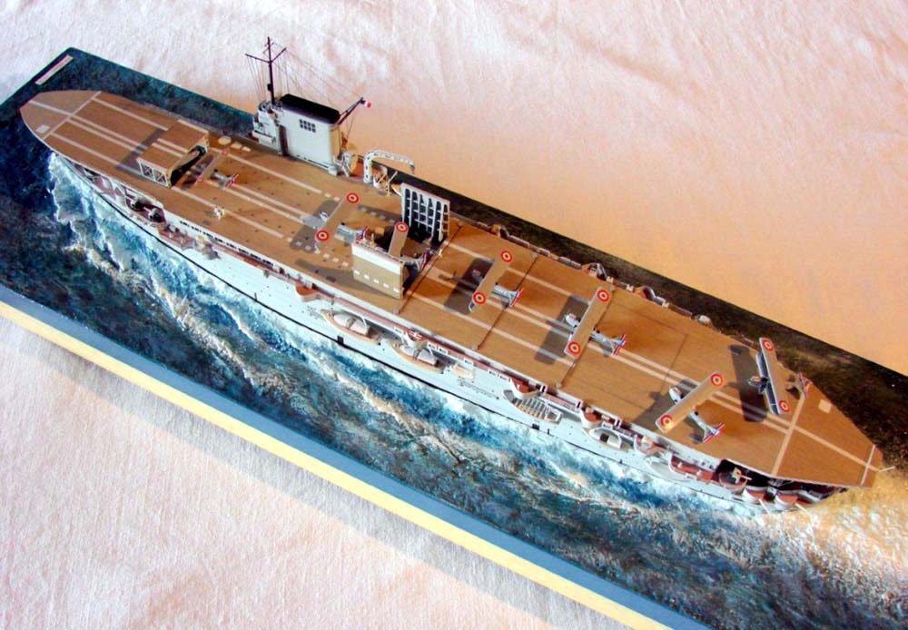 Good Day
great subject-I look forwarsd to your build of that interesting ship!
- I nealy bought one @ Telford in early 2000's -- but spent money other stuff and then had no funds left!!
here is a built model-right here at MW.com
cheers
http://www.modelshipgallery.com/gallery/cv/fr/bearn-400-lb/lb-index.html
Jim Baumann
[img]http://www.modelshipgallery.com/gallery/cv/fr/bearn-400-lb/bearn-21.jpg[/img]
|
|
|
|
Posted: Wed May 28, 2025 9:30 am |
|
|
|
|
|
| |
Post subject: |
Re: 1/400 MN Béarn |
|
|
|
Id love to see a well built Bearn!
Id love to see a well built Bearn!
|
|
|
|
Posted: Wed May 28, 2025 2:20 am |
|
|
|
|
|
| |
Post subject: |
Re: 1/400 MN Béarn |
|
|
Timmy C wrote: Oh wow, had no idea this kit existed! Wonder who did the moulds for L'Arsenal?
Looking forward to the build. I bought this kit when it first came out, but eventually sold it. I understand why they did it in 1/400, but that's one of the reasons I finally disposed of it. I wanted 1/350. I don't think I've ever seen one of these built up, looking forward to this. [quote="Timmy C"]Oh wow, had no idea this kit existed! Wonder who did the moulds for L'Arsenal?
Looking forward to the build.[/quote]
I bought this kit when it first came out, but eventually sold it. I understand why they did it in 1/400, but that's one of the reasons I finally disposed of it. I wanted 1/350.
I don't think I've ever seen one of these built up, looking forward to this.
|
|
|
|
Posted: Tue May 27, 2025 4:54 pm |
|
|
|
|
|
| |
Post subject: |
Re: 1/400 MN Béarn |
|
|
|
An interesting subject, and the history of production of the kit itself is quite interesting...
An interesting subject, and the history of production of the kit itself is quite interesting...
|
|
|
|
Posted: Tue May 27, 2025 1:24 pm |
|
|
|
|
|
| |
Post subject: |
Re: 1/400 MN Béarn |
|
|
|
Thanks for the interest. @Timmy: On the Heller forum some point out it looks like Heller plastic, and there is the scale of course. The PE has a "made in Czech" inscription, so that could be Eduard.
@steviecee: I saw it only yesterday on Ebay.fr.
@FFG: thanks. I believe after you showed them last year we had concluded that these plans are identical to the ones in my book. The overall plan is 1/500 and the sections are 1/400.
|
|
|
|
Posted: Tue May 27, 2025 4:40 am |
|
|
|
|

