I hope everyone here had a good start into the New Year 2025!
***************************************************************
Continuing with the bulkheadsProgress over December was slow, due to a couple of travels and a visitor over Christmas, but quite steady. All parts of the backbone have now been cut out and sanded/filed to shape. Dimensional accuracy was checked by placing the parts over a drawing on a LED-backlit board. The cant-frames, however, can only be finished, when the bulkheads have been glued in place.
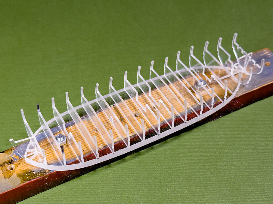 Collection of finished bulkheads
I was happy to see that the Plexiglas-sheet is dimensionally very accurate and fitting tightly into the milled slots in the base. This means no particular arrangements need to be made to ensure that they sit perfectly perpendicular on the base.
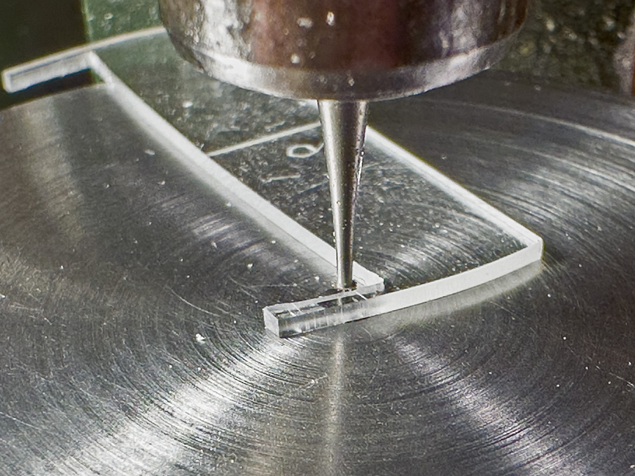 Milling a chamfer on the inside of the stanchions on micro-milling machine set-up as router
The bulkheads still required a bit of work. I thought it would be a nice detail to give the future bulwark stanchions a light chamfer over part of their length. This kind of edge-treatment was very common on many ship parts for both, aesthetic reason and to reduce the risk of splintering in case of an impact. It is not seen very often on models though. To this end I had made the router table last autumn. A 0.5 mm drill in a collet served as guiding pin and a small conical burr was used as router. The length of the chamfer was marked on the stanchions before milling it freehand. The result is difficult to photograph on the clear Plexiglas, but will become visible, once the model is being painted.
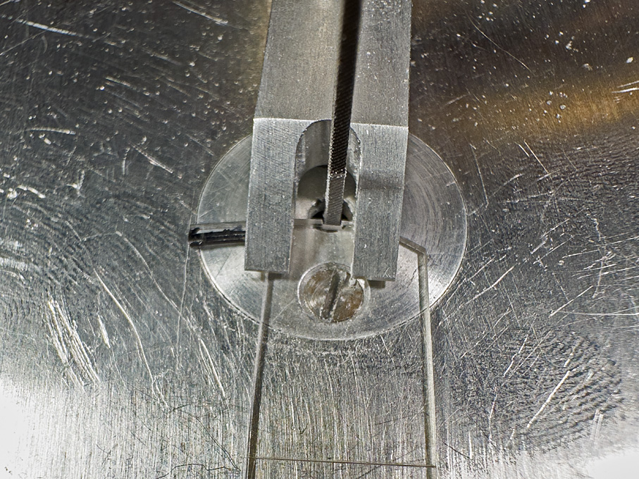 Filing notches for the wales on the shop-made filing-machine
Another operation was to cut shallow notches for the wale. The top-edge of the wale is marked in the original drawings and its width was taking from a table of scantlings of a similar ship. Having the wale fixed in that way will give a guidance for the later planking.
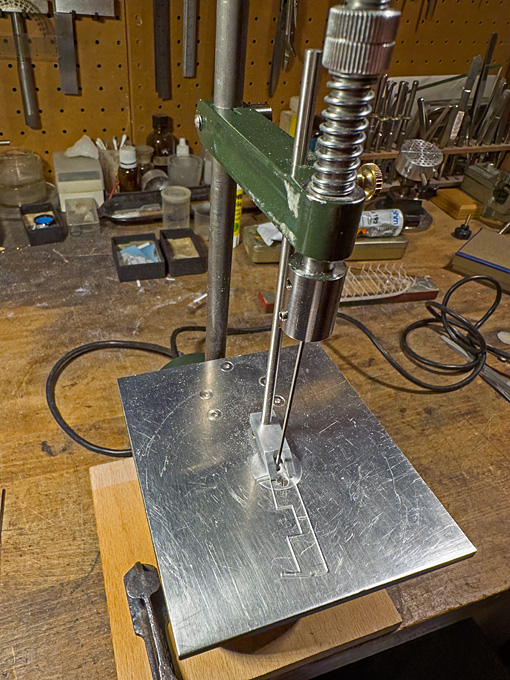 The shop-made filing-machine in action on the bulkheads
The notches were cut with a 1 mm x 1 mm fine machine file on the shop-made filing machine (
https://www.maritima-et-mechanika.org/tools/diefiler/diefiler.html). I was lucky to have been able to find on ebay some years ago whole boxes of unused machine files in various shapes, dimensions and cuts. A life-time supply of a tool that is not made anymore.
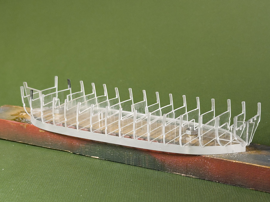 Finished bulkheads loosely put in place To be continued


