Thank you very much for your kind comments!
In between business-related absences from home, I managed to progress here a bit ...
****************
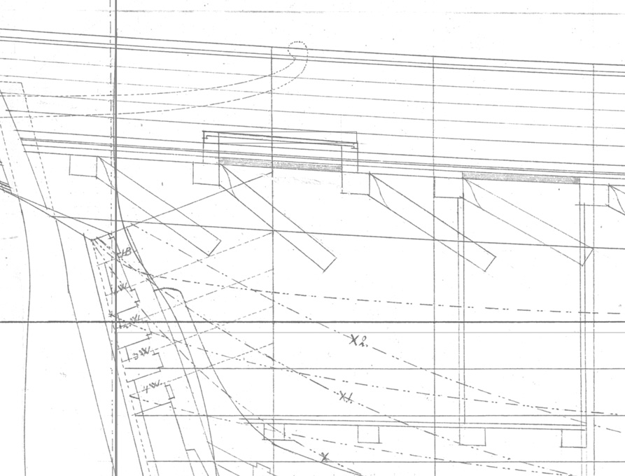
Cabin SkylightAs noted previously, the cabin skylight is a somewhat perilous position, but nevertheless contemporary drawings and some old models indicated, that they were of relatively lightweight construction. The actual construction is somewhat conjectural, but it seems that the hatch was covered by frame into which glass-panes were insert. Over this, there is a shallow roof-like structure with protective iron bars. In this arrangement, the glass-panes are not actually insert into the roof-like structure, but are at some distance below. The effect is, that even in the event that the iron bars are bent, the glass would not be touched. It also conceivable, that in the Baltic not real glass was used, but rather muscovite, which would be obtained by trade from Russia. In the event of very bad weather, the roof-like grille presumably could be replaced by a plain hatch cover.
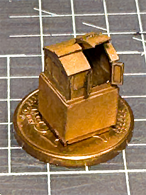
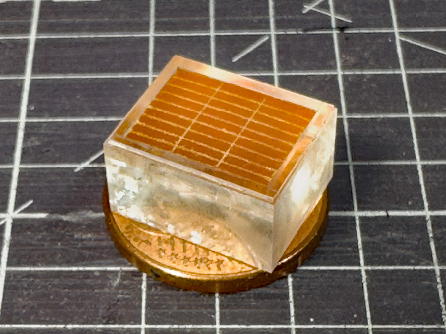
 Milling to shape of the acrylic glass core for the cabin skylight
This structure was built up in my preferred way, that is around a core of acrylic glass. It was milled to size from scrap piece of acrylic glass. For the ‘glass’ surface, I was able to use one of the original - as manufactured - surfaces, so no polishing was required. The high-speed milling with a fly-cutter a low feed-rate left almost transparent surfaces.
 Milling to shape of the acrylic glass core for the cabin skylight
 Milling of the recesses for the laser-cut frame parts
The parts for the roof-like structure were produced again with the laser-cutter from Canson paper. The structure was to be designed in two parts, namely the frame attached to acrylic core and the two roof halves with the grilles, to allow painting. During painting the horizontal pane will be masked off and the roof halves painted separately.
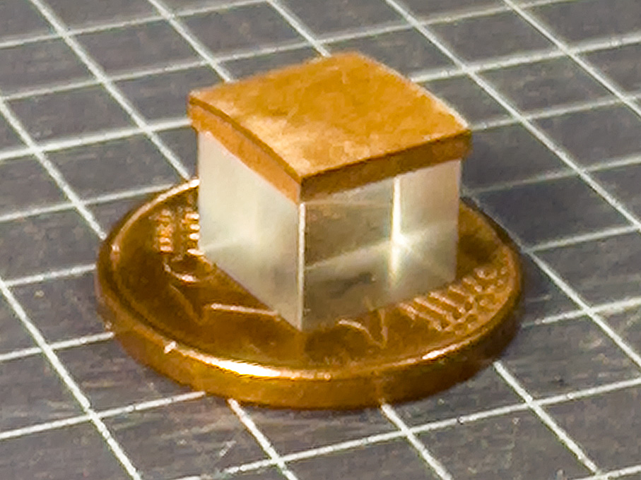
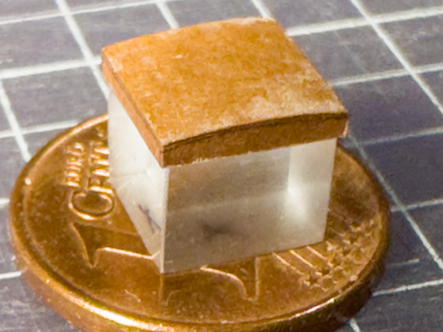
In order to ensure equal spacing of the ‘bars’, the roof was built up from three layers with the middle layers having notches. This layer was lacquered onto one of the outer layers and the ‘bars’ attached with drops of varnish – quite a fiddly bit of work and I am not entirely satisfied with the result. In the past, I made such parts from surface-etched brass and this seems to have worked better, but I didn’t want to set up everything for etching just a couple of small parts.
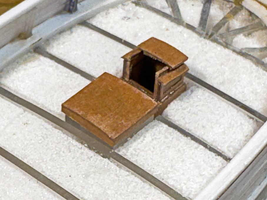
 Basic structure of the skylight, waiting to be painted and finally assembled
I prefer to defer painting to the late stages of the building process in order to avoid handling the painted parts as much as possible, so construction of the skylight stops here for the moment.
To be continued …