The Ship Model Forum

The Ship Modelers Source
It is currently Thu Jul 10, 2025 6:02 am

All times are UTC - 6 hours [ DST ]


Post new topic Reply to topic  [ 49 posts ]  Go to page Previous  1, 2, 3  Next
Author Message
PostPosted: Wed Dec 25, 2024 2:06 am 
Offline
User avatar

Joined: Sun Mar 07, 2010 12:01 am
Posts: 1677
Location: Corvallis, Oregon, USA
Eberhard,

Frohlliche Weihnachten fur dich!

_________________
A collision at sea will ruin your entire day. Aristotle


Report this post
Top
 Profile  
Reply with quote  
PostPosted: Wed Jan 08, 2025 5:29 pm 
Offline
User avatar

Joined: Wed Sep 28, 2011 12:04 pm
Posts: 1969
Location: Paris
I hope everyone here had a good start into the New Year 2025!

***************************************************************

Continuing with the bulkheads

Progress over December was slow, due to a couple of travels and a visitor over Christmas, but quite steady. All parts of the backbone have now been cut out and sanded/filed to shape. Dimensional accuracy was checked by placing the parts over a drawing on a LED-backlit board. The cant-frames, however, can only be finished, when the bulkheads have been glued in place.

Image
Collection of finished bulkheads

I was happy to see that the Plexiglas-sheet is dimensionally very accurate and fitting tightly into the milled slots in the base. This means no particular arrangements need to be made to ensure that they sit perfectly perpendicular on the base.

Image
Milling a chamfer on the inside of the stanchions on micro-milling machine set-up as router

The bulkheads still required a bit of work. I thought it would be a nice detail to give the future bulwark stanchions a light chamfer over part of their length. This kind of edge-treatment was very common on many ship parts for both, aesthetic reason and to reduce the risk of splintering in case of an impact. It is not seen very often on models though. To this end I had made the router table last autumn. A 0.5 mm drill in a collet served as guiding pin and a small conical burr was used as router. The length of the chamfer was marked on the stanchions before milling it freehand. The result is difficult to photograph on the clear Plexiglas, but will become visible, once the model is being painted.

Image
Filing notches for the wales on the shop-made filing-machine

Another operation was to cut shallow notches for the wale. The top-edge of the wale is marked in the original drawings and its width was taking from a table of scantlings of a similar ship. Having the wale fixed in that way will give a guidance for the later planking.

Image
The shop-made filing-machine in action on the bulkheads

The notches were cut with a 1 mm x 1 mm fine machine file on the shop-made filing machine (https://www.maritima-et-mechanika.org/tools/diefiler/diefiler.html). I was lucky to have been able to find on ebay some years ago whole boxes of unused machine files in various shapes, dimensions and cuts. A life-time supply of a tool that is not made anymore.

Image
Finished bulkheads loosely put in place

To be continued

_________________
Eberhard

Former chairman Arbeitskreis historischer Schiffbau e.V. (German Association for Shipbuilding History)

--------------------------------------------------------------------------------------------------------------------------------------------------------------------------------------------

Image Image Image Image


Report this post
Top
 Profile  
Reply with quote  
PostPosted: Thu Jan 09, 2025 10:16 am 
Offline
User avatar

Joined: Mon Jan 10, 2005 10:46 am
Posts: 2467
Location: Hoboken, NJ
Beautiful work. And I'm in LOVE with that disk sander!

_________________
We like our history sanitized and theme-parked and self-congratulatory, not bloody and angry and unflattering. - Jonathan Yardley


Report this post
Top
 Profile  
Reply with quote  
PostPosted: Thu Jan 09, 2025 10:44 am 
Offline
User avatar

Joined: Wed Sep 28, 2011 12:04 pm
Posts: 1969
Location: Paris
Thanks :thumbs_up_1:

The machine was built around parts of an antique watchmaking lathe: https://www.maritima-et-mechanika.org/tools/microgrinder/microgrinder.html.

The sanding disk is a a cheap diamond grinding disk of 40 mm diameter attached to a heavy turned flat brass disk with very thin industrial mounting tape. In this way it runs very flat without wobble.

_________________
Eberhard

Former chairman Arbeitskreis historischer Schiffbau e.V. (German Association for Shipbuilding History)

--------------------------------------------------------------------------------------------------------------------------------------------------------------------------------------------

Image Image Image Image


Report this post
Top
 Profile  
Reply with quote  
PostPosted: Tue Jan 28, 2025 4:26 pm 
Offline
User avatar

Joined: Wed Sep 28, 2011 12:04 pm
Posts: 1969
Location: Paris
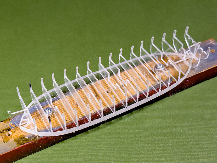
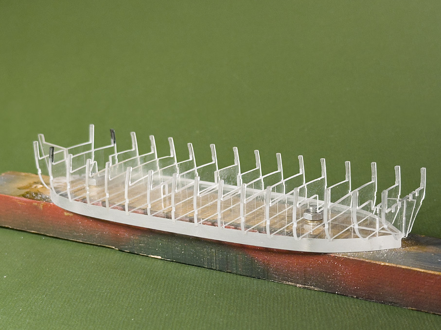
Filling the spaces between the bulkheads

After careful checking, the bulkheads were now cemented in place with Acrifix 192®, which is essentially liquid, unpolimerised Plexiglas®. This basically unifies two pieces with the same material, resulting in a virtually indestructible bond. Together with the tight fit in the milled slots, a very rigid framework resulted.

In order to facilitate fairing the bulkheads and prevent the very thin and flexible planking with styrene strips from sagging in, the space between them was filled with Rohacell® foam-board (https://history.evonik.com/en/inventions/rohacell), which is an acrylic equivalent to Styrofoam, but much harder and finer grained. I actually used material left over from the first project I built this way back in the early 1980s. It is sufficient to glue the pieces in place with general purpose glue.

Image
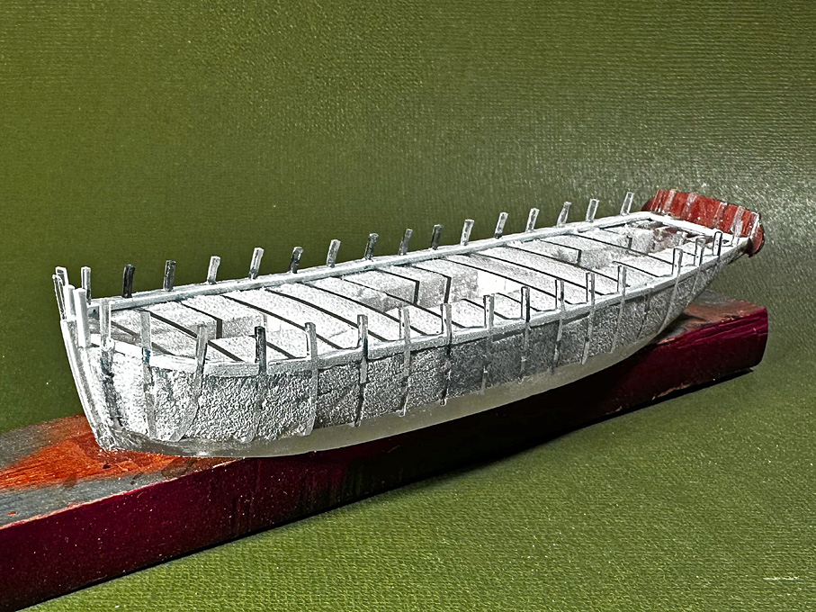
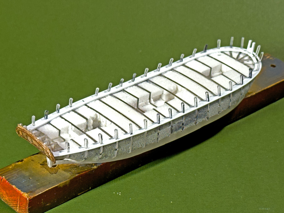
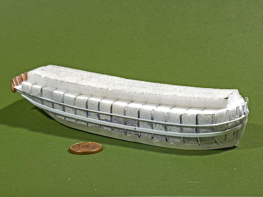
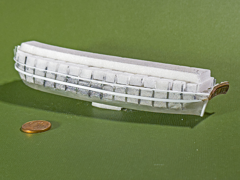
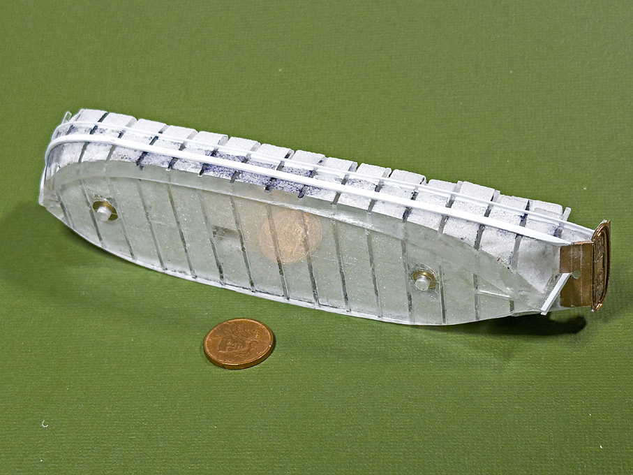
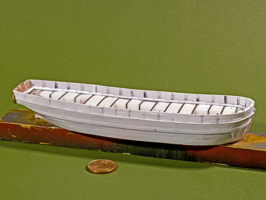
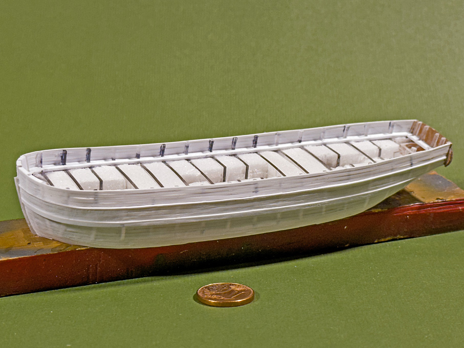
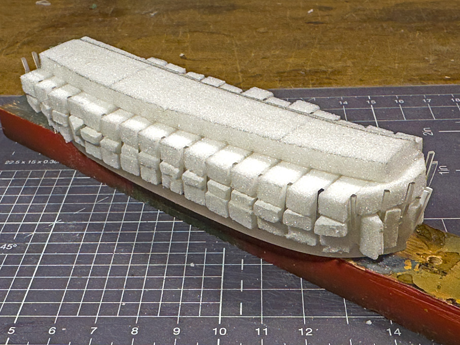
Spaces between the bulkheads filled with Rohacell® foam-board

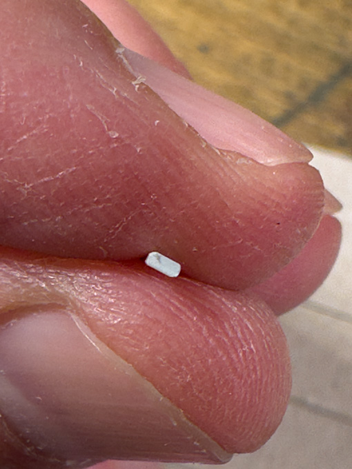
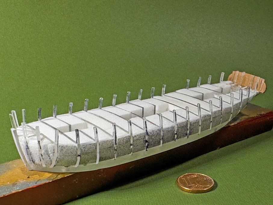
The bulwark stanchions are actually very fragile and to support them during fairing and being able to turn over the hull, the spaces between them were also filled with Rohacell™, but this unit was not glued down to the rest. Unfortunately, I still managed to snap one stanchion … Grrr.

Image
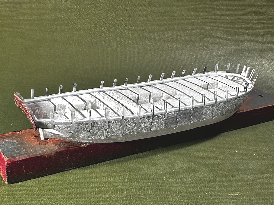
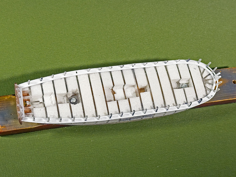
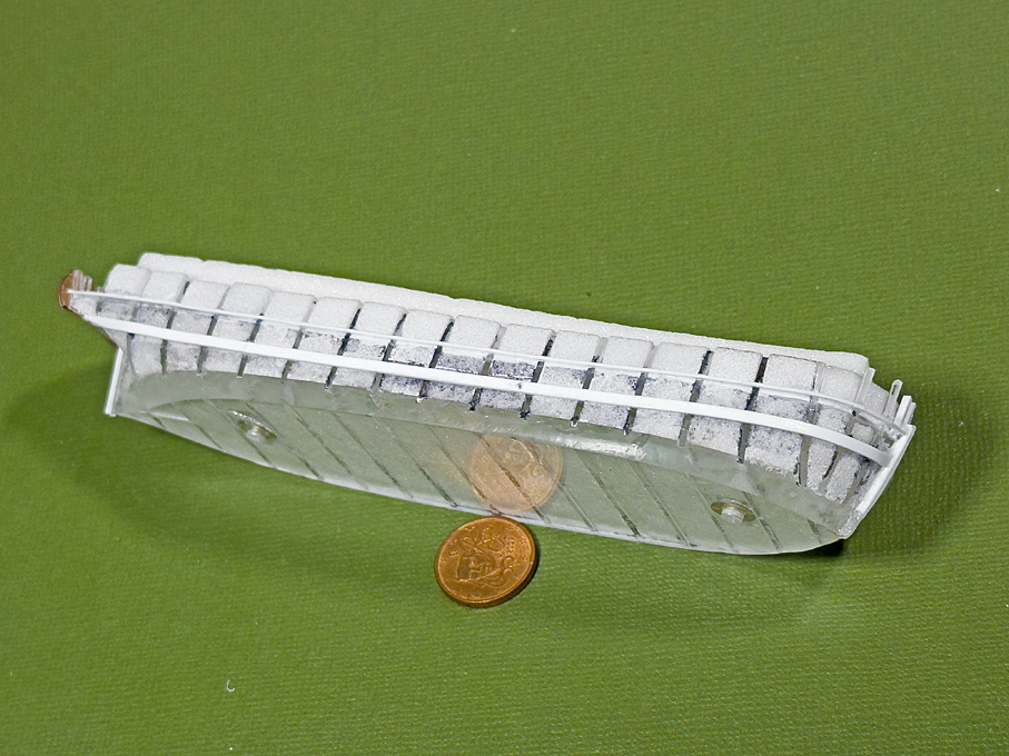
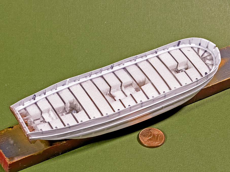
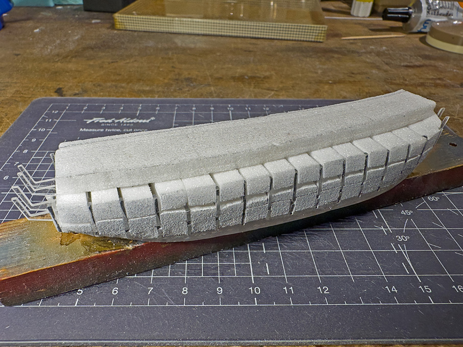
Spaces between the bulkhead filled with Rohacell® foam-board

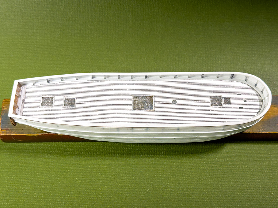
The fillers were ground back to the bulkheads, the edges of which were blackened with a permanent marker to indicate when I touched them. I then progressed to fair the bulkheads.

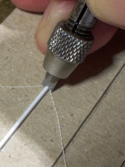
In the meantime, also pieces for the gill and the transom were drawn and laser-cut from Canson-paper and then soaked in zapon-varnish. At time when this ship was built, transoms often had carved elements and false windows, low-relief pilasters etc. as indicated in the original drawing. These were built up in two layers on a backing layer. Carved profiles were imitated with thin wire glued into place. The gill was also built up in three layers.

Image
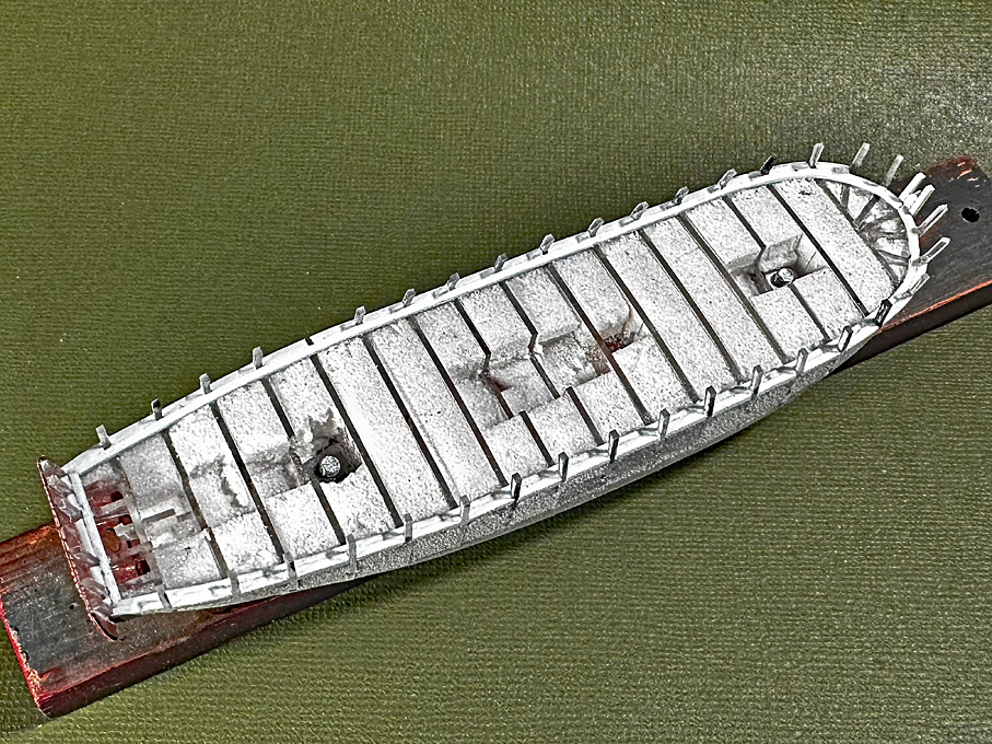
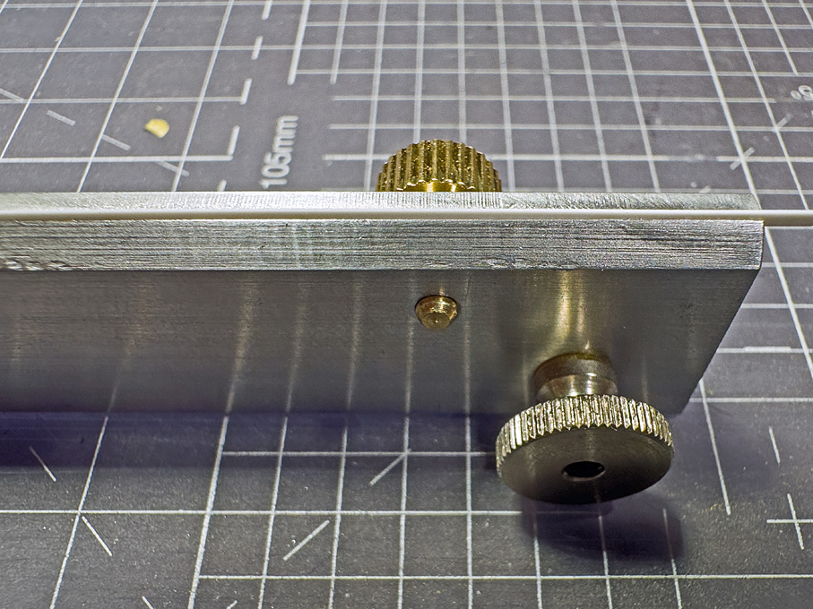
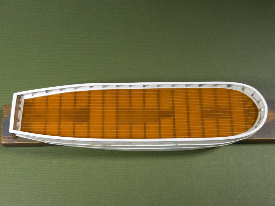
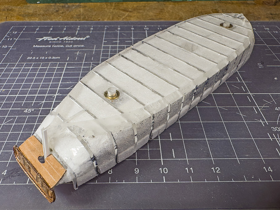
Looking up through the Plexiglas bottom-plate

When I offered up the gill piece to the ‘counter timbers’ and checked, how the hull planking would run up against it, I realised that something was wrong. The last bulkhead was too full in the lower part, but completely conformed with the line in the original drawings. After some head-scratching and careful analysis of all the lines in the original drawings, it dawned on me that, while the rearmost frame was projected into the same plane as the other frames, it was in fact the profile of a cant-frame the trace of which was drawn onto the waterline-drawing. Some rough lofting confirmed that suspicion.

Image
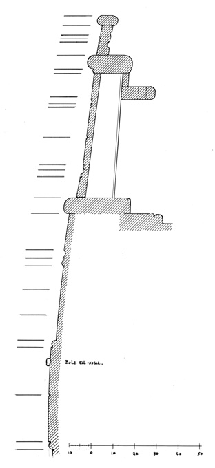
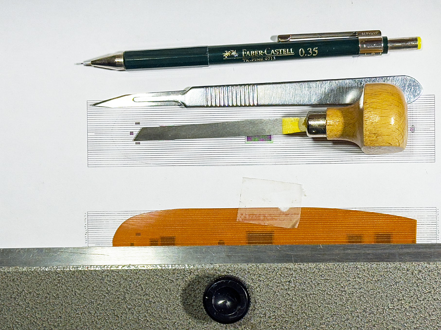
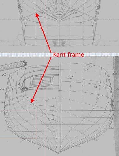
Extract from the original drawings with the misconceived cant-frames marked

There was no way of breaking off the faulty bulkhead due to the strong bond mentioned above. I had to shape the counter as is done in bread-and-butter construction. In fact, it might have been better to build up this area of complex curves from layers of Plexiglas right away. This kind of ships’ counters are not so easy to deduct from the lines drawings and to understand in its complex geometry – at least not, if you are not a trained naval architect.

Image
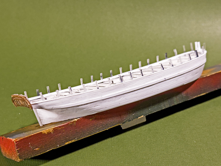
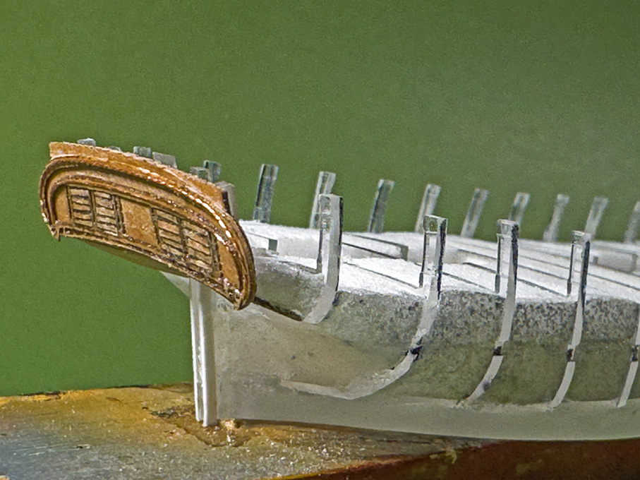
The correctly shaped counter and ornate transom

With the help of diamond burrs and files I managed to arrive at reasonable ‘free-form’ representation of the stern and trust that eventually the construction mistake will not be visible. After these corrections the gill-piece and the transom were glued into place.

Image
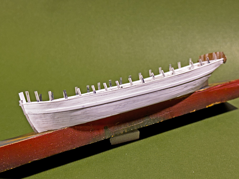
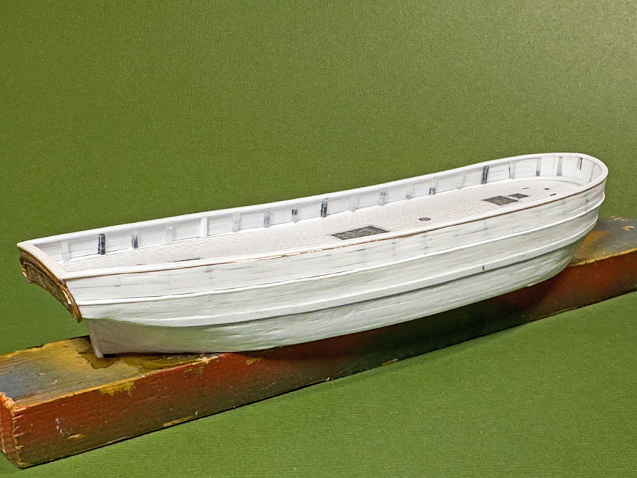
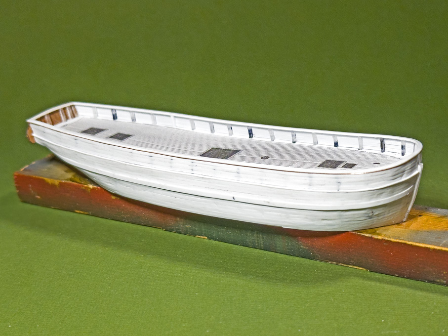
Bow view of the hull ready for the planking layout

Admittedly this looks rather rough at this stage …

To be continued

_________________
Eberhard

Former chairman Arbeitskreis historischer Schiffbau e.V. (German Association for Shipbuilding History)

--------------------------------------------------------------------------------------------------------------------------------------------------------------------------------------------

Image Image Image Image


Report this post
Top
 Profile  
Reply with quote  
PostPosted: Sun Feb 16, 2025 3:10 pm 
Offline
User avatar

Joined: Wed Sep 28, 2011 12:04 pm
Posts: 1969
Location: Paris
Slow Progress (as usual)

The run of the planking and their layout will be determined by three structural members, namely the rail on the bulwark as upper edge, the covering board, which marks the lower edge of the bulwark and the upper edge of which is marked in the original drawings, and the wales, the upper edge of which are also marked in the original drawings.

Image

In order to physically define the top edge of the covering board, the waterways have to be installed first. The consist of a 1 mm x 1 mm styrene strip running along the inside of the bulwark stanchions. This is thicker than the actual water ways would be, but the thickness includes that of the covering board inside the bulwark stanchions. The space between the stanchions was filled with small pieces of 1 mm x 1.5 mm styrene strip. This is a tad wider than needed, but allows me to sand them down to the actual profile outside of the stanchions. While in theory the stanchions are spaced equidistant, the filling pieces still required a bit of sanding to fit them snuggly.

Image

There are actually many different designs for the waterway/covering board arrangement and not any particular construction method is being followed here. The idea is to give the right visual impression after painting, not to follow prototype construction method. In fact, it would have been rather difficult to cut out the notches for the stanchions from the styrene strip representing the covering board at these dimensions, as would have been the prototype method.

Image

The arrangement will be completed by a 0.5 mm x 0.75 styrene strip that will be shaped to a half-round profile using a scraper fashioned from a piece of razor-blade and that will be cemented along the upper edge of the covering board.

To be continued ...

_________________
Eberhard

Former chairman Arbeitskreis historischer Schiffbau e.V. (German Association for Shipbuilding History)

--------------------------------------------------------------------------------------------------------------------------------------------------------------------------------------------

Image Image Image Image


Report this post
Top
 Profile  
Reply with quote  
PostPosted: Sun Feb 16, 2025 4:02 pm 
Offline
User avatar

Joined: Mon Jan 10, 2005 5:30 pm
Posts: 5569
Location: Nr Southampton England
its certainly looking boat-shaped
I will be intrigued to see the planking process

Best wishes
JB

_________________
....I buy them at three times the speed I build 'em.... will I live long enough to empty my stash...?
http://www.modelshipgallery.com/gallery ... index.html

IPMS UK SIG (special interest group) www.finewaterline.com


Report this post
Top
 Profile  
Reply with quote  
PostPosted: Sat Mar 01, 2025 6:41 am 
Offline
User avatar

Joined: Wed Sep 28, 2011 12:04 pm
Posts: 1969
Location: Paris
Coming soon ...

*****************

Quick update

In between travels I managed to attach the outboard part of the covering boards:

Image

Image

Image

I also scraped all the pieces to the same level, but some of the joints will need a bit of filling with putty to give a uniform appearance of a single board.

To be continued

_________________
Eberhard

Former chairman Arbeitskreis historischer Schiffbau e.V. (German Association for Shipbuilding History)

--------------------------------------------------------------------------------------------------------------------------------------------------------------------------------------------

Image Image Image Image


Report this post
Top
 Profile  
Reply with quote  
PostPosted: Thu Mar 06, 2025 2:33 pm 
Offline

Joined: Tue Feb 06, 2007 10:24 am
Posts: 2588
Location: Belgium
Well thought out and precise work! :thumbs_up_1: :thumbs_up_1: :thumbs_up_1:

I'm looking forward to the deck! I'm guessing you will add that before the hull planking?


Report this post
Top
 Profile  
Reply with quote  
PostPosted: Fri Mar 07, 2025 3:55 am 
Offline
User avatar

Joined: Wed Sep 28, 2011 12:04 pm
Posts: 1969
Location: Paris
Thankss !

Actually no, the deck will go in later, as it will be painted wood-simulation (as for SMS WESPE) and I have to complete all other paintwork first. At least that is the current plan.

_________________
Eberhard

Former chairman Arbeitskreis historischer Schiffbau e.V. (German Association for Shipbuilding History)

--------------------------------------------------------------------------------------------------------------------------------------------------------------------------------------------

Image Image Image Image


Report this post
Top
 Profile  
Reply with quote  
PostPosted: Sat Mar 08, 2025 3:51 pm 
Offline
User avatar

Joined: Wed Sep 28, 2011 12:04 pm
Posts: 1969
Location: Paris
Digression 3

As the start of the planking is imminent, I had to think about a way to shape thin, narrow and long strips of styrene. A clamp is needed that can hold strips down to 1 mm width, 0.25 mm thickness and 150 mm length securely. In addition, the strips have to be held in a way that allows to slightly bevel the edges, if needed. The idea was to clamp the material between to flat metal bars of sufficient stiffness.

Image

I happened to have to matching aluminium bars of 20 mm width and 3 mm thickness that once formed part of a jig and could be repurposed.

The two bars were tightly clamped together and milled flat on the top so that they abut with sharp edges. Then, one edge was bevelled to 45° to give clearance for bevelling the styrene (or wood for that matter) strips. Unfortunately, the table travel of my mill is not long enough to do the milling in one set-up and I could not clamp the whole length of the bars in the vice, which resulted in some chatter marks. Not beautiful, but still functional.

Image

The clamping action is exerted by three thumb-screws for which holes were drilled and tapped.
I stuck a strip of Tamiya masking-tape at about 0.5 mm distance from the top edge in order provide a stop for very thin and narrow material.

Image

Now the clamp has to be tested in anger, to see, whether it really proves useful – not all of my home-made tools that felt like a good idea, really turned out to be that practical.

Building log to be resumed soon …

_________________
Eberhard

Former chairman Arbeitskreis historischer Schiffbau e.V. (German Association for Shipbuilding History)

--------------------------------------------------------------------------------------------------------------------------------------------------------------------------------------------

Image Image Image Image


Report this post
Top
 Profile  
Reply with quote  
PostPosted: Sun Mar 09, 2025 12:28 pm 
Offline
User avatar

Joined: Wed Sep 28, 2011 12:04 pm
Posts: 1969
Location: Paris
Installing the wales

It was fortunate that the upper edge of the wale was marked in the original drawings. I had transferred this to the bulkheads and cut appropriate notches. Somehow, however, these notches turned out to be not very useful as I would have to score the whole core of the hull accordingly, which would have been messy. In the end, I ignored them, though used their upper edge as guidance for placing the wales. I have no information on their dimension, but thought that a width of 240 mm = 1.5 mm looked about right on the hull. They would have been probably composed of two thick planks. For the thickness I choose 0.75 mm, as the hull-planking will be 0.5 mm thick. Contemporary pictures and naval construction books show both options, smooth hulls, where the thicker wales are not visible and step-changes in thickness. I think smooth hulls became fashionable around the middle of the 19th century, but in the Baltic they were always lagging a bit behind, so I went for the stepped design.

Image

Perhaps this is a problem of building up the planking around a solid core, but the way how the wales run against the gilling at the stern caused me some head-scratching. The point where the upper edge of the wale touches the gilling is marked in the original drawings, but it is not clear, where the lower edge touches it. While the wales have an easy run all along the ship, at this point some twisting is needed.

Image

I had not done any planking with styrene before. It turned out to be quite simple: unlike wood, it does not have grain of course and strips can be easily bent and twisted even across the long sides. Pulling the strips around a round piece of e.g. steel causes the strips to curl and one can thus achieve a nice pre-bending without the need of much clamping force, when cementing them on.

Image

Nevertheless, the wales were attached with the recently discovered artificial nail cement, that is a mixture of light-curing acrylic cement and cyanoacrylate. It sets fast, but not so fast that no adjustment would be possible. I let it seep under the wales attached to the hull with Sellotape. Hereby I worked from the more complicated stern forward in more or less long sections, depending on the curvature.

Image

Final clean-up will be done, once the rest of the planking has gone onto the full, with the view to blend everything nicely together.

To be continued ...

_________________
Eberhard

Former chairman Arbeitskreis historischer Schiffbau e.V. (German Association for Shipbuilding History)

--------------------------------------------------------------------------------------------------------------------------------------------------------------------------------------------

Image Image Image Image


Report this post
Top
 Profile  
Reply with quote  
PostPosted: Tue Mar 18, 2025 4:19 pm 
Offline
User avatar

Joined: Wed Sep 28, 2011 12:04 pm
Posts: 1969
Location: Paris
Planking the hull

In principle planking this hull with styrene strips is not very different from planking with strips of wood. The styrene strips have the advantage that they can be more easily bent across the breadth. One can also shape them like metal by stretching and compressing until they conform to the shape of the solid hull. A disadvantage is that they are less stiff than wood and easily ‘sag’ in, say in thicknesses of les than 0.5 mm, but it also depends on the distance between the frames.

Image

Planking proceeded up and down from the wales and down from the covering board. The Evergreen styrene strips are sawn from sheets as is evidenced by saw-marks on the narrow sides. This results in slight variations of their width, typically up to 0.1 mm wider for a 1 mm wide strip. This has to be considered, when planning the plank layout.

In the end, I didn’t actually use my new plank-clamp much. It was easier to hold the strips short with the edges upright and to scrape the edge with a scalpel to reduce the width in a controlled fashion. There was not much need to bevel the edges. The styrene cement, of course, softens or dissolves the material, which allows it to be pushed together closely, obviating the need for bevelling at least for material of 0.5 mm thickness or less.

Image

Unlike for woodworking, not many specialised tools are needed. I use a scalpel, the tools that in the old days was used to rub-on lettering comes handy to press on the strips, a large diamond nail-file for thinning down strips, and cutting-tweezers as watchmakers use them for shortening strips to length. The latter have the cutting edge bevelled only on one side, allowing for clean cuts without squashing the material. I also made small scrapers from a piece of razor-blade, held in a pin-vise. Steel-wool of various grades helps to blend-in parts or lightly round edges.

Image

The pictures show the planking after cleaning up by sanding and scraping, but before puttying any gaps that may have occurred. I went for some slight irregularity of the surface, as may be observed in a well-used older wooden ship. This livens up an otherwise somewhat sterile styrene surface.

To be continued …

_________________
Eberhard

Former chairman Arbeitskreis historischer Schiffbau e.V. (German Association for Shipbuilding History)

--------------------------------------------------------------------------------------------------------------------------------------------------------------------------------------------

Image Image Image Image


Report this post
Top
 Profile  
Reply with quote  
PostPosted: Tue Apr 01, 2025 3:51 pm 
Offline
User avatar

Joined: Wed Sep 28, 2011 12:04 pm
Posts: 1969
Location: Paris
Planking the bulwarks

The planking of the bulwarks follows the same procedure as that for the hull, but had to be handled much more careful, as the inside will be visible and there will by no adjustments possible by sanding or scraping. The main reason for the latter is, that the planks are of scale thickness (0.25 mm) and profiled.

Image
Section through a bulwark drawn by Friis-Pedersen (1980)

As can be seen from the two images above and below, it was not uncommon to give the edges of the planks a decorative profile by using an appropriate profile plane.

Image
Bulwark of a Swedish jagt, photographed in November 2023 in Stockholm

I had been exploring various ideas for creating these profiles on tiny 1 mm x 0.25 mm styrene ‘planks’ uniformly and consistently close to the edges. In the end I decided on a simple and rather makeshift solution: a steel ruler was taped to a small cutting-mat to serve as guide for the very flexible strips. The chosen tool is an old-style ruling pen, of which I have several knocking about in my drawer of draughting utensils. This was set so that it creates a groove close to the opposite edge, when run along the edge of the strip. This works only for strips of uniform width.

Image

It was important to prevent the styrene strips from softening too much during gluing, therefore only tiny drops of liquid styrene cement were applied to each stanchion.

Image

Somehow the alignment of the bulkheads was not as perfect as I was hoping for, resulting in some bulges. I hope I will be able to correct/hide this somehow.

Another problem is that the styrene strips of scale thickness are rather floppy, so that edge-alignment is rather difficult. I hope that I can also sort this out.

Once the planks were on, I installed the hawse-timbers between the stem and the cant-frames in the bow.

Image

Next on will be the rails.

To be continued …

_________________
Eberhard

Former chairman Arbeitskreis historischer Schiffbau e.V. (German Association for Shipbuilding History)

--------------------------------------------------------------------------------------------------------------------------------------------------------------------------------------------

Image Image Image Image


Report this post
Top
 Profile  
Reply with quote  
PostPosted: Tue Apr 01, 2025 4:29 pm 
Offline
User avatar

Joined: Mon Jan 10, 2005 5:30 pm
Posts: 5569
Location: Nr Southampton England
Looking good--and much " boatier " than before....

:thumbs_up_1: :thumbs_up_1:
JB

_________________
....I buy them at three times the speed I build 'em.... will I live long enough to empty my stash...?
http://www.modelshipgallery.com/gallery ... index.html

IPMS UK SIG (special interest group) www.finewaterline.com


Report this post
Top
 Profile  
Reply with quote  
PostPosted: Sun Apr 13, 2025 12:54 pm 
Offline
User avatar

Joined: Wed Sep 28, 2011 12:04 pm
Posts: 1969
Location: Paris
Thanks, much appreciated :thumbs_up_1:

*****************************************

Fitting the rails

The rails are 0.75 mm x 1.50 mm styrene strips on top of the bulwark and a 0.75 mm x 2.00 mm strip over the stern. The edges of the strips are rounded.

Image

To this end I cut a scraper from a piece of razor-blade which is held in a short pin-vice. The strip is held in a simple jig made from cardboard. Strips of cardboard were cut with clean and vertical edges and glued to a cardboard-base so that styrene strips of 0.25 mm, 0.50, and 0.75 mm thickness can be wedged into the resulting notch, holding it straight and vertical.

Image

In this way a clean and uniform profile of the styrene strip can be achieved quickly.

Image

The styrene strips then were pre-bend, holding them lightly in round-nosed pliers and by ‘massaging’ them around my thumb to make them conform to the sheer-line as closely as possible. They then were glued onto the stanchions and the top bulwark strake using styrene-cement.

Image

As can be seen from the cross-section shown in the previous post, the profile of the rail may be even more sophisticated with some cornice planed in. I simulated this my lacquering a 0.1 mm copper wire into the outboard corner under the rail.

Image

The next step will be puttying up any small gaps that have developed during the planking process.

Image

As one can see on the pictures, I also started to work on the deck by making a paper template for it.

To be continued …

_________________
Eberhard

Former chairman Arbeitskreis historischer Schiffbau e.V. (German Association for Shipbuilding History)

--------------------------------------------------------------------------------------------------------------------------------------------------------------------------------------------

Image Image Image Image


Report this post
Top
 Profile  
Reply with quote  
PostPosted: Mon Apr 14, 2025 2:57 am 
Offline
User avatar

Joined: Mon Jan 10, 2005 5:30 pm
Posts: 5569
Location: Nr Southampton England
That is neat tool making with the chisel blade cut out....

Th result is really good!

:thumbs_up_1:

JIM B

_________________
....I buy them at three times the speed I build 'em.... will I live long enough to empty my stash...?
http://www.modelshipgallery.com/gallery ... index.html

IPMS UK SIG (special interest group) www.finewaterline.com


Report this post
Top
 Profile  
Reply with quote  
PostPosted: Sun Apr 20, 2025 1:24 pm 
Offline
User avatar

Joined: Wed Sep 28, 2011 12:04 pm
Posts: 1969
Location: Paris
Thanks to Jim and all the other visitors of this log :thumbs_up_1:

*********************************************************

Fitting the deck

The deck is made from 0.4 mm thick Bakelite-paper. I find it easier to engrave the deck-seams consistently into this harder material with my tools, then into the softer styrene sheet. Perhaps I should get some day one of those hooked engraving tools the plastic modellers use (I have the suspicion these are the same tools as dentists use to scrape of ‘plaque’ – I have one of those and perhaps should have tried).

I first printed out the deck-drawing, cut out the shape and fitted it to the ship. Using the paper template, the shape was cut from the Bakelite with a small margin. This then was fitted very carefully in an evening’s session. Fitting started from the stern working forward, taking off material with a diamond nail-file while checking the fit after a couple of strokes.

A tight fit is important, as the whole idea is to paint the deck off-ship to avoid a complex masking exercise. Also, the painting process (as described in the build-log for SMS WESPE) would be difficult to exercise within the constraints of the bulwark.

Image
Tools used for engraving the deck seams

The fitted deck was taped to a printout of the deck with the planks marked as guidance for engraving. A heavy steel ruler ensured straight lines. First, the plank seam was marked with a scalpel to provide some ‘tooth’ for the graver. Then a narrow engraver’s graver was run twice along the ‘seam’ to clean out the shallow groove. Once the engraving was completed, the whole deck was thoroughly brushed with a rotary bristle-brush to remove burrs.

I ended up doing this three times, as in the first two attempts I lost count and cut a skewed seam. This is unrepairable, so I had to start all over again. However, the first fitted deck provided a good template, speeding up the fitting process: after scoring the material with a scalpel around the edges of the template, one can break the new deck out of the bakelite sheet. Only comparatively little fitting was required then.

Image

In fact, scoring the bakelite-paper with a scalpel twice and then breaking along the line is a quick and clean way of getting straight cuts that just require a bit of sanding with a diamond file.

The next step would be to cut out the openings for the companionways and hatches. However, these have to be tight fits to them and it will be easier to first build those and then file out the openings – back to the drawing-board for some time.

To be continued …

_________________
Eberhard

Former chairman Arbeitskreis historischer Schiffbau e.V. (German Association for Shipbuilding History)

--------------------------------------------------------------------------------------------------------------------------------------------------------------------------------------------

Image Image Image Image


Report this post
Top
 Profile  
Reply with quote  
PostPosted: Wed May 14, 2025 3:23 pm 
Offline
User avatar

Joined: Wed Sep 28, 2011 12:04 pm
Posts: 1969
Location: Paris
Crew companionway

The deck of the Rahschlup was flush, no raised quarterdeck or any deckhouses as such. Only companionways gave access to the crew quarters and the after cabin respectively. All in all, a very spartanic arrangement.

Image
Companionway on the reconstruction project for the galeas FÖRLIG WIND, Skeppsholmen, Stockholm (https://www.arbeitskreis-historischer-s ... ppsholmen/)

The length of the companionways and of the hatches can be taken from the side elevation drawing, but their width has to be inferred from common practice of the time. Likewise, their construction had to be inspired by photographs of appropriate restoration projects. A typical construction method seems to have been panelled sides. Other examples include simple vertical or horizontal staves that fill the space between the corner posts. Two narrow doors give access, together with a sliding roof section. The rails on which this cover slides seems to have been of varying degrees of complexity.

Image

I usually built such companionways around a core in Plexiglas that has been milled to shape. For this project, however, I wanted to show them open with some interior details, so that a construction method somewhat closer to the prototype had to be chosen.

Image

The different parts were drawn and cut out with the laser-cutter from 0.1 thick Canson paper. Each side was laminated from three layers for the actual companionway and two more layers for the coamings using Zapon varnish. The roof and the sliding cover were built up from two layers. The sliding rails were constructed from narrow laser-cut strips. The doors are also built up from three layers.

Image

Unlike on the prototype, the companionways and ‘coamings’ reach down to a horizontal layer in the hull in order to provide a reference for their height above the deck, when installed.

Image

As with all such parts, they may look a bit rough in the close-up pictures, but once painted and from a normal viewing distance they look very good (hopefully …).

To be continued …

_________________
Eberhard

Former chairman Arbeitskreis historischer Schiffbau e.V. (German Association for Shipbuilding History)

--------------------------------------------------------------------------------------------------------------------------------------------------------------------------------------------

Image Image Image Image


Report this post
Top
 Profile  
Reply with quote  
PostPosted: Fri May 30, 2025 2:28 am 
Offline

Joined: Tue Feb 06, 2007 10:24 am
Posts: 2588
Location: Belgium
Beautiful work Eberhart!

Evergreen makes grooved styrene sheets (usually advertised as railcar siding or V-groove siding):
https://evergreenscalemodels.com/collec ... car-siding
https://evergreenscalemodels.com/collec ... r-siding-1
https://evergreenscalemodels.com/collec ... ove-siding

There are three thicknesses (0,5 mm, 0,75 mm and 1 mm), and can be very useful for wooden decks, as the grooving is very crisp and regular. There is a nice range of 'plank' widths to choose from.


Report this post
Top
 Profile  
Reply with quote  
Display posts from previous:  Sort by  
Post new topic Reply to topic  [ 49 posts ]  Go to page Previous  1, 2, 3  Next

All times are UTC - 6 hours [ DST ]


Who is online

Users browsing this forum: No registered users and 6 guests


You can post new topics in this forum
You can reply to topics in this forum
You cannot edit your posts in this forum
You cannot delete your posts in this forum
You cannot post attachments in this forum

Jump to:  
Powered by phpBB® Forum Software © phpBB Group