The Ship Model Forum

The Ship Modelers Source
It is currently Wed Jul 16, 2025 12:13 am

All times are UTC - 6 hours [ DST ]


Post new topic Reply to topic  [ 301 posts ]  Go to page Previous  1 ... 9, 10, 11, 12, 13, 14, 15, 16  Next
Author Message
PostPosted: Mon Aug 19, 2013 3:22 pm 
Offline
User avatar

Joined: Sun Mar 13, 2005 11:51 am
Posts: 2432
Location: Belgium
Been thinking about those, I'm pretty sure I'd find what I need from BECC, like the draught marks I bought there. Yet it has to come from UK etc. I hate hick-ups when I'm running, so painting was the only way. The transfers would have looked better for sure, but it would have also stopped the build for a while. There's many details that I can finish, but I don't feel in a detail mode nowadays.
Due to the trials I got more motivation to do the large and very visible stuff, so it looks better on the water. I guess now, with the deckhouse nearly complete, I'll have to go back to smaller detail until the end of the build.

Thanks for thinking along though. Sometimes I don't know what's on the market since we don't really have shops anymore in Belgium who have large stocks of materials on the shelves (only 2 as far as I know and they're not exactly close to my place). The draught marks as proposed by Dave were a rescue!

_________________
The merchant shipyard


Report this post
Top
 Profile  
Reply with quote  
PostPosted: Mon Aug 19, 2013 6:01 pm 
Offline
User avatar

Joined: Sat Jan 22, 2005 10:18 am
Posts: 4131
Location: Liverpool
Hi Roel Your Chaconia sails really well , I am impressed . BECC produce lettering in Arial font, 11 sizes from 2mm up to 25mm and in 10 solid colours . black ,white, gold, silver, red, blue, yellow, green, orange, and purple.
Dave Wooley :thumbs_up_1: :thumbs_up_1: :thumbs_up_1: :thumbs_up_1:


Report this post
Top
 Profile  
Reply with quote  
PostPosted: Mon Aug 19, 2013 7:09 pm 
Offline

Joined: Sat Jan 30, 2010 12:30 am
Posts: 57
For dry transfer lettering, try taking a look at Woodland Scenics. I'm sure there are others out there. They have quite a bit and for the most part a few different font sizes come on one sheet.

http://woodlandscenics.woodlandscenics. ... ics/page/1


Report this post
Top
 Profile  
Reply with quote  
PostPosted: Tue Oct 22, 2013 11:14 am 
Offline
User avatar

Joined: Sun Mar 13, 2005 11:51 am
Posts: 2432
Location: Belgium
So back to the build. It looks like I've underestimated (like not underestimating this ship was an option :heh: :huh: :doh_1: ) some of the work. Certainly the detailing of the compressor room. I sort of hoped to just place it and get on with the build, but considering the wise words of Timmy C that detailing and quality of a model also depend on consistency, I had to do a lot more detailing than I expected.
The superstructure has the spray system installed, so the compressor room should have that as well.
So starting from the beginning, first the rain water drains from the top to the bottom. Then the horizontal spray system, which has a different diameter on different places.
After that I'll have to add a couple more pipes and only after that I'll be able to really place it.
I encountered one problem with that. I made the base on the deck for the "old" compressor room, which was slightly different in size. I'll have to adjust that base. Furthermore the deck isn't entirely flat, so I'll have to fill and sand the edge, which will be trouble.
I'm thinking of putting a small layer of milliput on the bottom of the room and then push it into place and cut off the excess milliput. Afterwards slight sanding (which will be difficult with all the detailing in place) and painting of the lower edge.

Here are a couple of pics of the piping all around. The three ladders on the front bulkhead will be delicate as well. perhaps I'll place them once the room is in place. The holes for their supports are already drilled after all.
Sometimes I really don't see the end of this ship, but I guess the only way is to keep advancing step by step. Each time I take a big hurdle I think it's going to go easy to make big progress afterwards, but it's not... :Mad_6:

Most of the diameters and placing are estimates based on pictures and experience, since I don't have detailed plans of that.

Image

Image

Image

_________________
The merchant shipyard


Report this post
Top
 Profile  
Reply with quote  
PostPosted: Tue Oct 22, 2013 11:42 am 
Offline
User avatar

Joined: Tue Apr 17, 2007 9:18 am
Posts: 1993
Location: Brasil
Hi Roel I agree with you, the detailing of a ship when you have the drawings for this, torma most beautiful however more work, more time consuming, and everything else that the builder has to offer.
however when it comes to a stage of this construction and get to see the model resembles the original ship, then a certain pleasure takes care of all of us.
is anyway, s details are wonderful and will bring great quality at a scale model, but we must keep our resolve at all times.
satisfaction will one day be forever :thumbs_up_1:
p.s. your model looks great my friend


Report this post
Top
 Profile  
Reply with quote  
PostPosted: Tue Oct 22, 2013 3:12 pm 
Offline
User avatar

Joined: Sat Jan 22, 2005 10:18 am
Posts: 4131
Location: Liverpool
Hi Roel I find drawings provide only a part of the information to build a model . pictures another part but perspective can create an illusion of a part being what it is not . Lastly experience and insight provide the rest. The model looks great . :thumbs_up_1: :thumbs_up_1: :thumbs_up_1:
Dave Wooley


Report this post
Top
 Profile  
Reply with quote  
PostPosted: Mon Oct 28, 2013 6:23 am 
Offline
User avatar

Joined: Sun Mar 13, 2005 11:51 am
Posts: 2432
Location: Belgium
Well decided not to break my head over that compressor room placement. I now installed all the equipment on the poop deck. Kind of like kit building, since most of that equipment was already made a couple of years back :huh: Anyway now was the time to place it I guess. Any progress is good at this point.
I also installed the compressor room with a milliput border, but that only partly succeeded.
The Milliput didn't really stay well on the edge and when I pushed the compressor room down some of it was inside rather than outside. This means I'll have to add more milliput from the outside and that's a pretty delicate job with all the stuff already in place around it.
Also sanding will be difficult since the details on the compressor room bulkheads might get damaged. I alsready decided to remove some of the drain pipes in order to facilitate any sanding on the edge. I had to place these drains to be able to bend the spray system piping (horizontal pipes on the top) around them. I guess if I carefully remove this pipe, the spray system can remain untouched, only some extra glue traces will be visible on that drain pipe.

Anyway, here are some pictures of the poop deck installations. One more part, an emergency towing winch will have to be installed. This was not part of the original design since it's not on the plans. Nowadays such devices are obligatory for all tankers, the composition depends on the tonnage.

Image

Image

Image

_________________
The merchant shipyard


Report this post
Top
 Profile  
Reply with quote  
PostPosted: Mon Oct 28, 2013 6:31 am 
Offline
User avatar

Joined: Tue Apr 17, 2007 9:18 am
Posts: 1993
Location: Brasil
Hi Roel i'm loving your model :woo_hoo:


Report this post
Top
 Profile  
Reply with quote  
PostPosted: Fri Nov 01, 2013 11:56 am 
Offline
User avatar

Joined: Sun Mar 13, 2005 11:51 am
Posts: 2432
Location: Belgium
Thanks Norberto.

I've been doing the same for a while now, measuring, drilling holes for position/strengthening pins and eventually gluing some details in place. I've been waiting for some time to go out sailing again. I had to fix the lubrication point on the shaft and fix one of the electrical connections first though.
Today, although plagued by drizzle and a whole day overcast, I did give it a try, probably the last time for the winter time. This time I crossed, shortly, from the "fishing part" of the yachting port to the real yachting part, under the bridge to the big brothers...

Sorry for the blurry pics, taking pics and sailing if you're alone is not that easy, lighting conditions weren't too great either.
Image

Image

Image

Image

Image

Image

I've also finished the tank ventilation fans, all 4 remaining ones, I also made 4 additional bollards (apparently I miscounted last time) and all mooring winches are now installed.

Edit: I just weighed her, as she was in the water, and she weighed 21kg. As you perhaps saw, she was more or less evenkeel in this case, yet still a couple of cm below her summer draft mark (that would make around 30kg in scale). I'll have a look at the pics and see on the real plan if I'm close to the scale weight for that draft (and therefore close to the real hull shape).
I think I'll keep the weight like this, but trim her slightly more aft. I added the weight forward now, so the prop actually came up and it gave a funny sound. On the other hand she did steer even better this time.

_________________
The merchant shipyard


Report this post
Top
 Profile  
Reply with quote  
PostPosted: Fri Nov 01, 2013 4:43 pm 
Offline

Joined: Sat Sep 17, 2005 9:19 am
Posts: 1554
Very nice work Roel!


Report this post
Top
 Profile  
Reply with quote  
PostPosted: Sun Dec 22, 2013 8:05 am 
Offline
User avatar

Joined: Sun Mar 13, 2005 11:51 am
Posts: 2432
Location: Belgium
Thanks Pieter,

A small update now. I'm doing lots of work on her, but you hardly see it. During my last deployment I didn't get to make anything, but I made a page with scetches of the larger parts that I still had to make. I wrote all measurements next to it as well, so I don't really have to remeasure. This allows me to work much faster than before as I always went back and forth between computer for pictures and plans to measure and then back again and so on. Now I just have that page and I can continue cutting parts and assembling them.

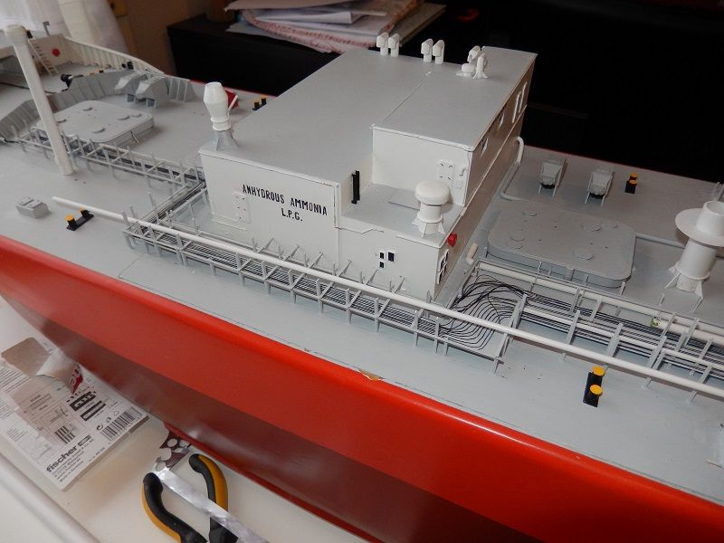
Since I got ahead of schedule on those parts I also continue on the build itself. With the deck house in place I could finally continue on the missing midship part of the pipe rack. It's proving to be a real head breaker as some parts are hard to see on any picture and I have to start from the deck up.
So for now I've added the sea water overboard line from the cargo heater (not in place yet) to the deckhouse. I'm busy on the supports for that line. At the same time I'm also putting the first part of the big sea water supply line from engine room to the deck. That's the first big line that will be placed on the piperack since it's also the most outboard one. In this dry fit you can also see the biggest diameter line, the Inert Gas line, just to fit.

Image

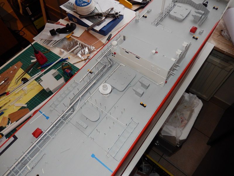
This is the reason why the deck house first had to be placed, so parts of the piperack are connected to it.
Image

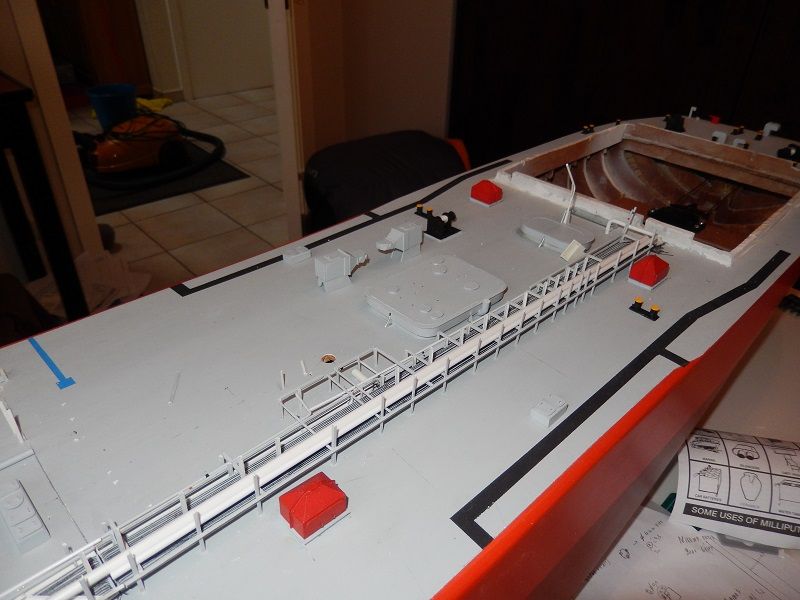
Here is the first fit of some of the large pipes. All styrene tubing. I can go two directions now, either finish part of the aft piperack, with all piping to the aft tank etc in place up till the midship hatch. Or I can continue line by line all the way forward. Not sure which direction to take yet.
Image

For all the bends in the piping I have different solutions. For anything up to 1.5mm styrene tubing, I can bend them by hand without any major deformation.
For 2mm I'll insert a brass wire. For 2.5mm I have some electrical construction wire, a copper wire which is jacketed by a sort of rubber, I bought the white version. This is made for bending, so it actually works nice! Just have to make my bends and then glue it to the styrene tubes.
For 3mm I use the 1.5mm copper core from the above wire and insert it in the tube itself. Because the tube is then filled entirely by something incompressible, it bends nicely till 90° without major deformation.
4mm, I still have to test, I guess I'll try again the copper core method, otherwise perhaps I'll insert the complete electrical wire (2.5mm).

This way I'm avoiding the boiling water method etc. since that would be very tedious due to the high amount of turns and all the fitting issues on the ship itself.

The only issue I haven't resolved for now is a method to make cooling vanes for the different cargo pump electro motors. I've tried to make a mini "accordeon" ^^^^ shape from alu foil. It actually worked, but it's still slightly too high and very difficult to fit. I've been thinking about small pieces of wire, like Jaguar did for his 1/200 motors, but that won't look too good either... Any tips for that are welcome.

_________________
The merchant shipyard


Report this post
Top
 Profile  
Reply with quote  
PostPosted: Tue Dec 24, 2013 7:51 pm 
Offline
Site Admin
Site Admin
User avatar

Joined: Sat Jan 08, 2005 4:31 pm
Posts: 3579
Location: Plattsburg, Missouri
Impressive. Did I tell you I used to fill anhydrous tanks for farmers?

_________________
Timothy Dike
Owner & Administrator
ModelWarships.com


Report this post
Top
 Profile  
Reply with quote  
PostPosted: Sat Dec 28, 2013 11:35 am 
Offline
User avatar

Joined: Sun Mar 13, 2005 11:51 am
Posts: 2432
Location: Belgium
Thanks, and, no you didn't tell me... We used to be the largest ammonia supplier around the world. Not sure how that is nowadays. Either way, most of the trade is indeed used for fertilizer (certainly in US) and for explosives (for mining industry and probably demolition).

Here are a few pics to make my trick for bending more clear.
This is the wire I use, with the insulation it has a diameter of 2.5mm, so for that tubing it can use it straight away:

Image

and in this pic you see most of the things I use for 3mm tube. So first I drill a 1.5mm hole/tunnel in the 3mm tube by hand drill. Then I cut a similar length piece of the construction wire, and cut off the jacket. You can see that in the picture. So all that remains is an approx 1.5mm copper wire piece. That I insert insid the styrene tube. Then I use the pipe bender to make the turn and I cut the corner off the rest of the tube. This enables me to work more accurate than when I would try to bend the hole pipe in one piece. I can also not drill the entire length of piping, so better this way. I leave some excess copper wire, as you can see in the examples in the pictures, in place to use to center and reinforce the connection with the rest of the piping.
Image

For 4mm piping I use the same method, but I curve around a 5mm drill to make the turn as the pipe bender is only suitable for 3mm piping. For 2.5mm I can use the wire itself with the insulation. For 2mm and below I can bend the styrene without any copper wire or heating.

The turns you see here will be for one of the main pipes, but first I need to find a way to make some convincing valves.

This method works to avoid any flatening or deformation of the piping. If you use a hollow pipe, it wil stretch and flatten around the bend.

_________________
The merchant shipyard


Report this post
Top
 Profile  
Reply with quote  
PostPosted: Mon Dec 30, 2013 7:54 am 
Offline
User avatar

Joined: Tue Apr 17, 2007 9:18 am
Posts: 1993
Location: Brasil
I was seeing your model and observing the wonderful details that did a great job and still do, but the browsing model goes very well in the water.
work on deck is very good and well executed,
I am very grateful to see that model I love tankers.
take this opportunity to wish a happy new year to you and all friends here Forum :wave_1: :smallsmile: :smallsmile:

p.s. i will go back to my hull now :cool_2:


Report this post
Top
 Profile  
Reply with quote  
PostPosted: Sat Jan 04, 2014 4:43 am 
Offline
User avatar

Joined: Sun Mar 13, 2005 11:51 am
Posts: 2432
Location: Belgium
Thank you very much Norberto! Happy New Year to you and everybody reading this topic!

A small New Year update.
With all the questions about that piping and valves out of the way, I decided to do this first on the aft part before continuing the pipe rack midship.
Also did some final work on the aft pipe rack. Some of the more complicated things are the vapor dome piping.
This is all just dry fit to measure and construct the piping. I didn't glue it yet as some of the pipes go through, under and over the others.

Image

Image

Image

The big U shape is there to allow for shrinking of the piping when the pipe is cooled down/cold.
Next step is "terminating" the piping, placing it on the rack, putting U-bolts to keep them in place (not sure yet, since it will involve a great deal of drilling work, potentially destroying the piperack), and then putting the end connections on it.

_________________
The merchant shipyard


Report this post
Top
 Profile  
Reply with quote  
PostPosted: Sun Jan 05, 2014 4:19 pm 
Offline
User avatar

Joined: Tue Apr 17, 2007 9:18 am
Posts: 1993
Location: Brasil
very nice job on main deck. the resolution of tube bending is fantastic as well the solution of tub bender and insulation wire.
i have one tanker to do to after i do Bismarck.
the arrangment of the tubes on deck as similar i will do (some day....)
well good job my friend :woo_hoo: :cool_2:


Report this post
Top
 Profile  
Reply with quote  
PostPosted: Sun Jan 05, 2014 5:30 pm 
Offline

Joined: Fri Sep 25, 2009 6:28 am
Posts: 571
Location: Near Veenendaal, The Netherlands
Looking great!
Good luck with the piping that is still to come, there is no shortage of pipes on the decks of tankers...

Greetings Josse

_________________
Making a complete new Well Enhancer, again scale 1:75.


Report this post
Top
 Profile  
Reply with quote  
PostPosted: Sat Jan 11, 2014 3:57 pm 
Offline
User avatar

Joined: Sun Mar 13, 2005 11:51 am
Posts: 2432
Location: Belgium
Yeah, gas carriers for sure. Oil tankers are rather simple. There's only liquid and some inert gas piping on deck, main liquid piping is is anyway from pump room to manifold in that case.
On gas carriers you have liquid, vapor (from tanks to liquefaction) and condensate (from liquefaction back to tanks), besides those you have also some booster pumps and heater on deck, with their own piping along with inert gas, sea water etc. The midship part will be a real difficulty... That's one of the reasons why I started with the piping aft. I'm kind of postponing the research on that midship spaghetti. :heh:

Anyway some progress.
To take a small break I decided to first make something decent out of that styrene tube that acted as foremast. Just to make sure that next time she looks a little more professional on the water :big_grin:
Image

Image

Still have to add the lights, horn and flag lines. I also came to the conclusion that the forecastle is still missing a considerable amount of detail!

And I've continued a little on the aft piping again, "terminating" the liquid header to the pumps and back to the tank. I guess I'm nearly ready to start painting and glueing of some pipes. First have to put some additional detail and supports to line them up correctly.
The small pieces on the line are various flanges and valves. I still have to glue them and put some finishing touch.

Image

_________________
The merchant shipyard


Report this post
Top
 Profile  
Reply with quote  
PostPosted: Fri Jan 17, 2014 7:03 am 
Offline
User avatar

Joined: Tue Mar 30, 2010 3:58 am
Posts: 94
Location: Caboolture, Queensland, Australia
Wow, she is looking amazing.

_________________
One thing you never want to hear from the Ammo tech - "Oops"


Report this post
Top
 Profile  
Reply with quote  
PostPosted: Fri Jan 17, 2014 1:20 pm 
Offline
User avatar

Joined: Sun Mar 13, 2005 11:51 am
Posts: 2432
Location: Belgium
Continued a little bit. Done some final jobs and first layer of paint on several objects/sub-assemblies.
Here is the crane base, the upper part and jib I'll have to rebuild since they are of wrong dimensions.
Image

Some deck view, I've built part of the condensate system for aft cargo tank, slowly the tank dome is getting crowded. I've also nearly finished the discharge valves of the pumps aft, just a stanchion (performing job of spindle) and a wheel. I saw some 5-spoke wheels at the scalelink site, but with shipping it'll cost a lot. I'll have a look around in some train supply stores etc.

Image

Close-up of the valves on the condensate system. The change in diameter of the line is real. The thick part is just insulation, the wire near the valves is the actual pipe. Both pictures are of course very zoomed in. The actual diameter of the wire is 0.8mm, the part with "insulation" is 2mm styrene.

Image

Image

As you can see I've also made small supports with holes, those holes will receive a U-bolt to keep the pipe in place.
Up till now I've also glued the vapor line in place because I had the yellow for the color coding. I'm stuck there since I don't have any dark orange available for the liquid line and gradually I have to fix them to get the final lengths and lay-out of certain parts.

_________________
The merchant shipyard


Report this post
Top
 Profile  
Reply with quote  
Display posts from previous:  Sort by  
Post new topic Reply to topic  [ 301 posts ]  Go to page Previous  1 ... 9, 10, 11, 12, 13, 14, 15, 16  Next

All times are UTC - 6 hours [ DST ]


Who is online

Users browsing this forum: Majestic-12 [Bot] and 5 guests


You can post new topics in this forum
You can reply to topics in this forum
You cannot edit your posts in this forum
You cannot delete your posts in this forum
You cannot post attachments in this forum

Jump to:  
Powered by phpBB® Forum Software © phpBB Group