Thank Martin, me too.
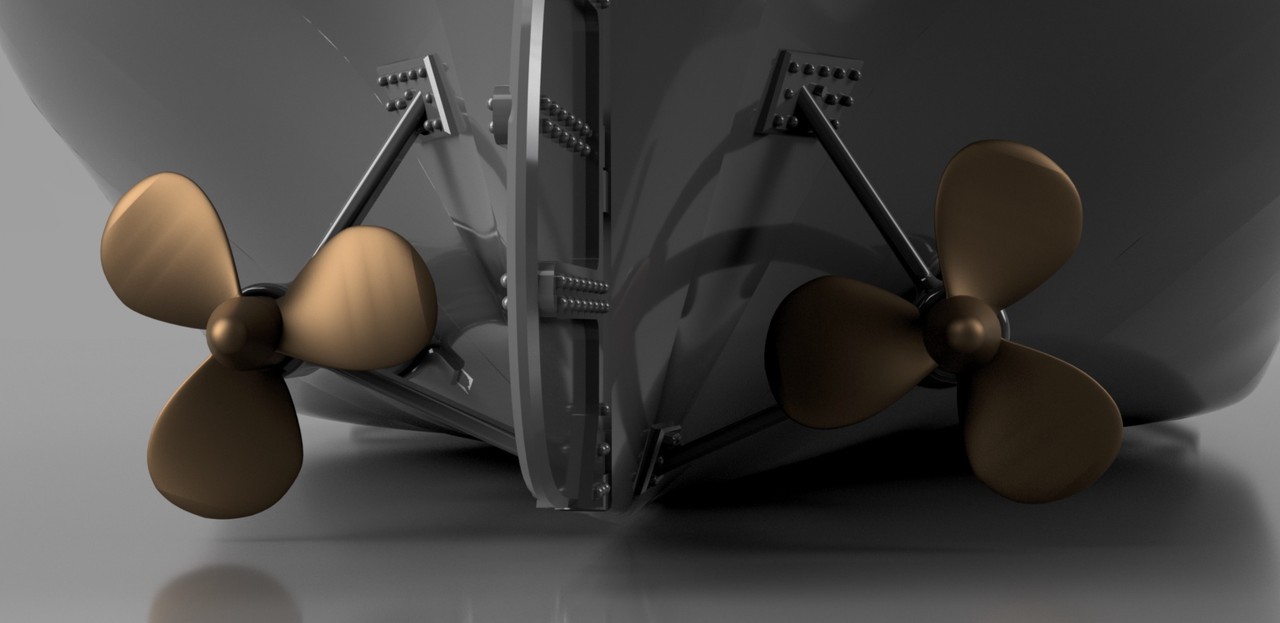
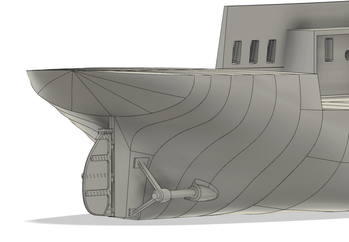
Propeller day today, "the test" so dreaded by any budding amateur modeller like me, especially when you have no plan but your photos, it's already not bad and better than nothing...

This is my second propeller modeling, the first one for the T2 tanker was not perfect, just acceptable, but it allowed me to develop a relatively fast and efficient method for what we do with it at our scale and for a non-functional propeller.
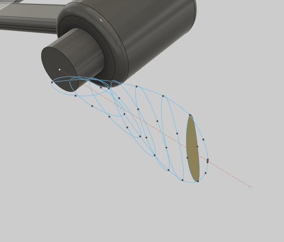
I start by drawing a base profile at the root of the propeller shaft, it will serve as a reference, I incline it at about 45° from the propeller shaft, it's according to the pitch we want to give, I draw an axis perpendicular to the axis of the shaft passing through this profile it will also be my reference axis for the propeller blade. I copy the basic profile at regular intervals along this axis, here 6.
I don't have any pictures of this phase.
Then I twist the 6 identical profiles by orienting them with an offset of a few degrees identical or not to each profile, we can make a linear step increase if we want to perfect the drawing.
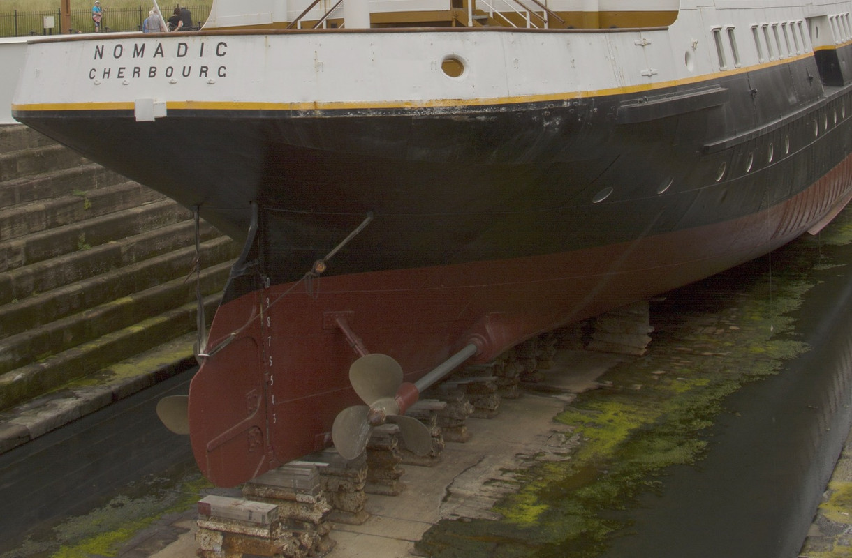
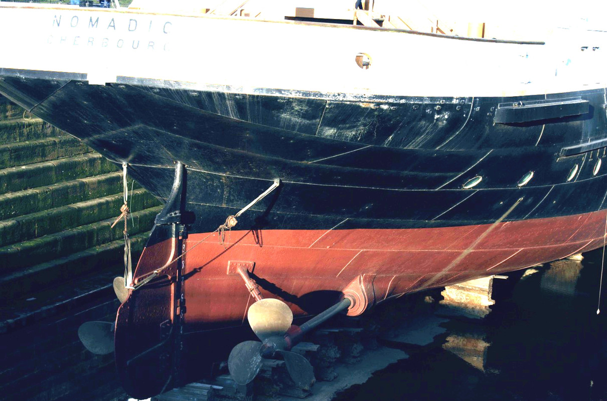
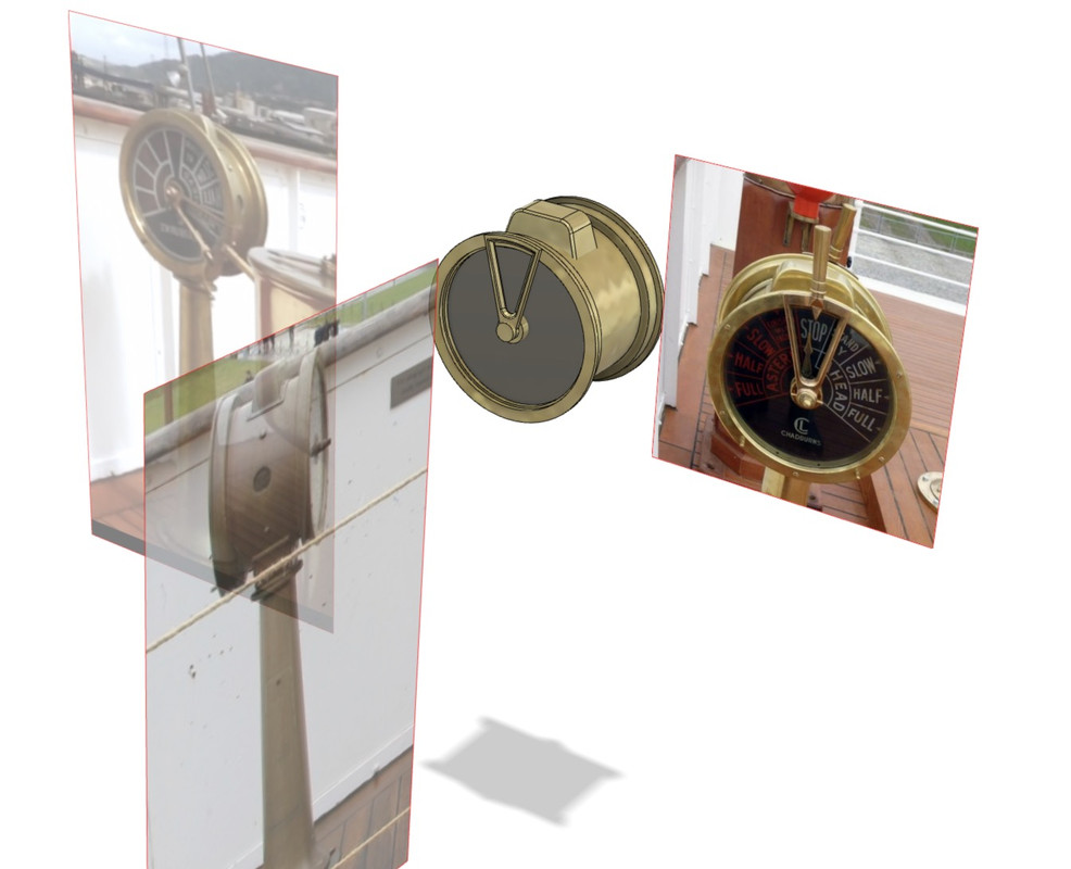
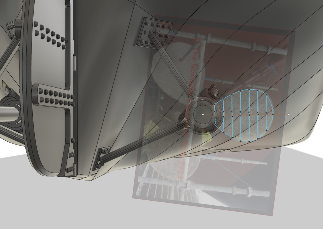
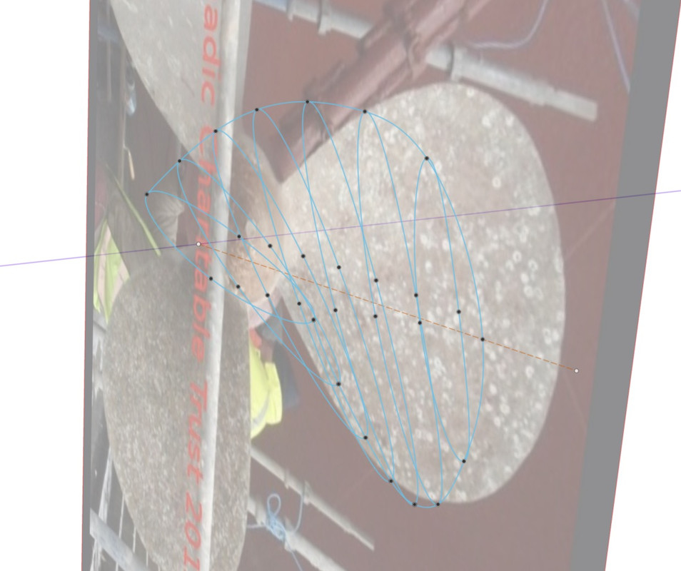
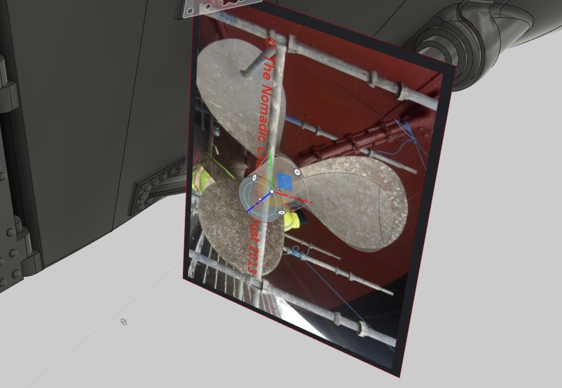
Once the profiles are shifted, I am lucky enough to have a front photo of the propeller in question, I put it as a transparent layer on my drawing to reproduce the shape, because all my profiles are the same size for the moment.
You just have to increase the size of the profile on each side to reach the edge of the helix of the photo, so you always have the particular shape of each helix.
Then I connect by a curved elastic line all the ends of the profiles, going to the last one, but not further, not like in the picture. It will be necessary to proceed differently for the blade tip, the last segment.
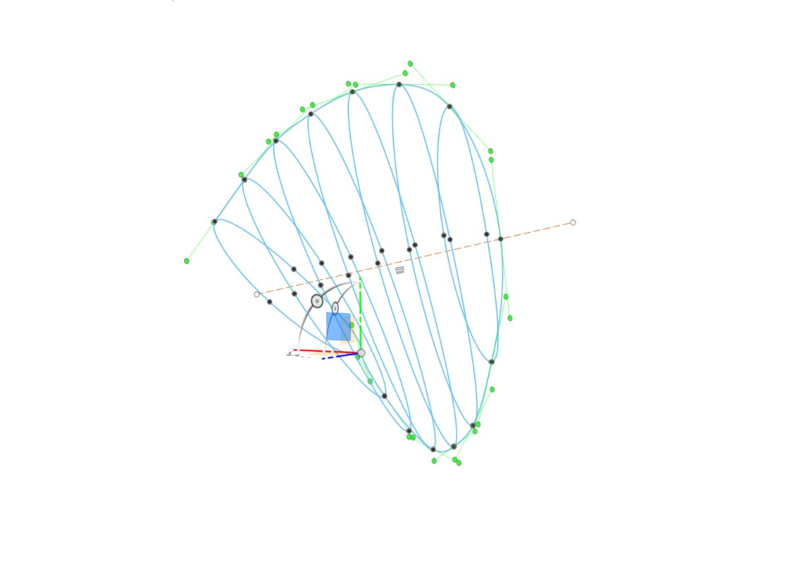
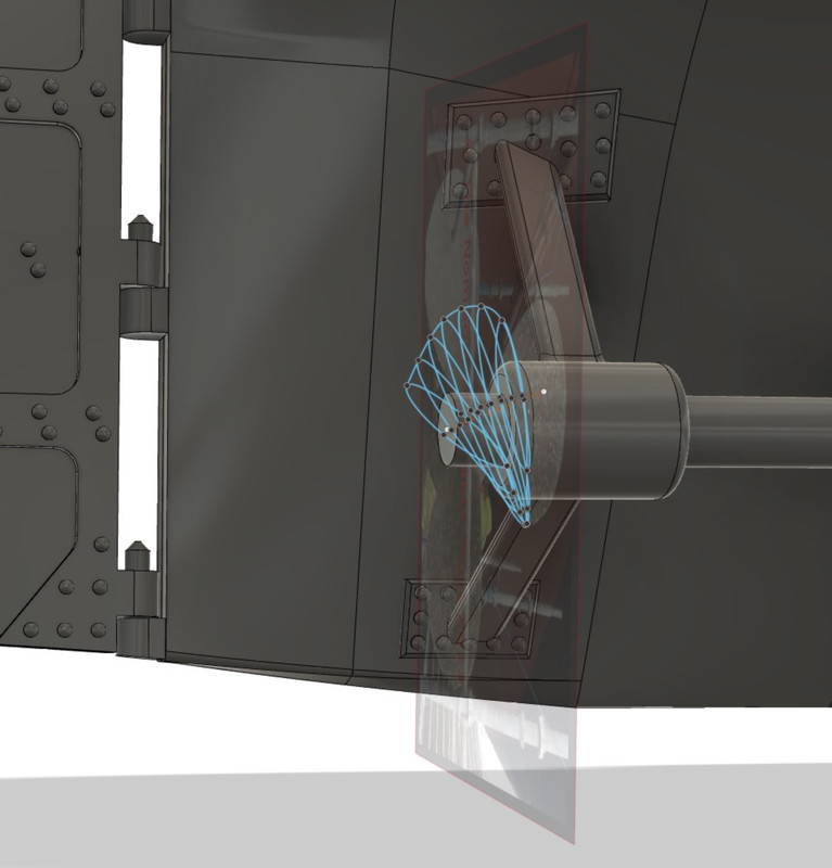
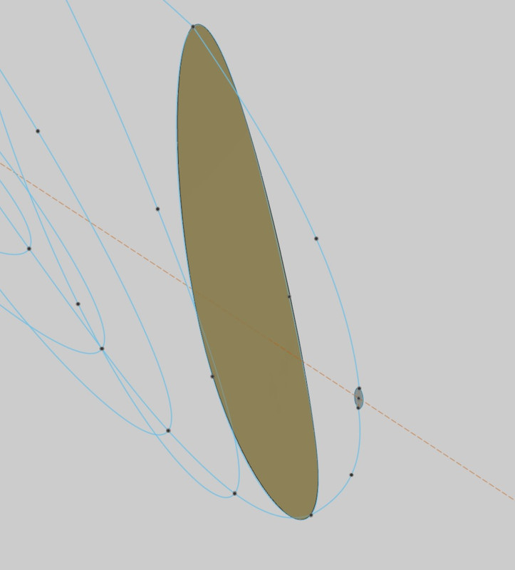
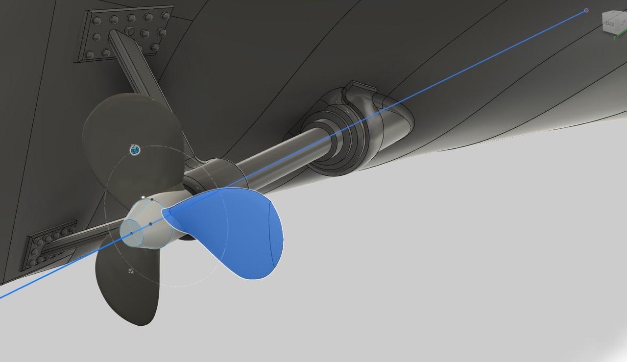
On Fusion, as the profiles were not flat themselves, I had to use the Patch function to create temporary surfaces without thickness in "3D" to represent my profiles. I'm going to use it to use the LOFT.
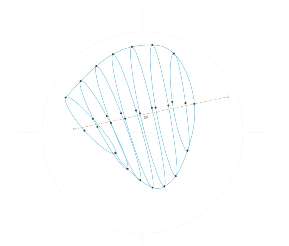
This is the right representation, the pale end is not yet drawn.
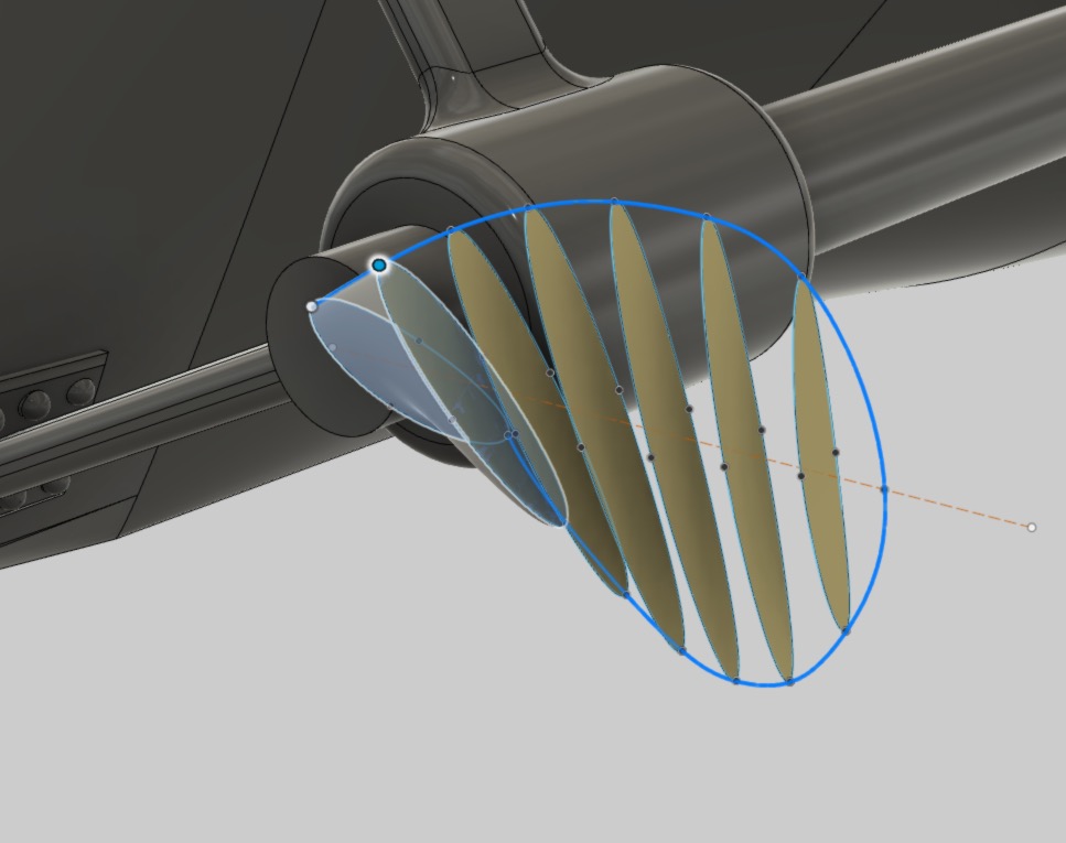
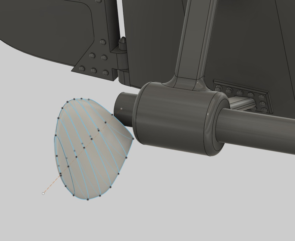
Here I have used the LOFT function to create my full 3D volumes.
At the end of the blade I create a micro profile, which you won't see because it's tiny, but it's essential to create the blade tip. From this micro profile I draw two elastic lines towards the next profile, taking care that their curves are very soft and tangent to the other profiles, it is necessary to add points on the curves if necessary to perfectly adjust the edges.
We see here the micro profile at the end of the blade, we can make it even smaller of course so that it does not appear at the scale of the propeller.
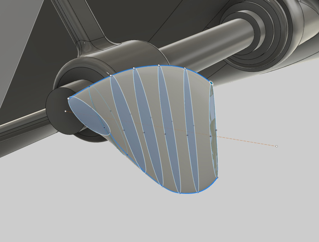
The loft function can then be used to finish the blade tip.
Drawing of the propeller hub. I added a profile at the root, I was a bit short in blade length.
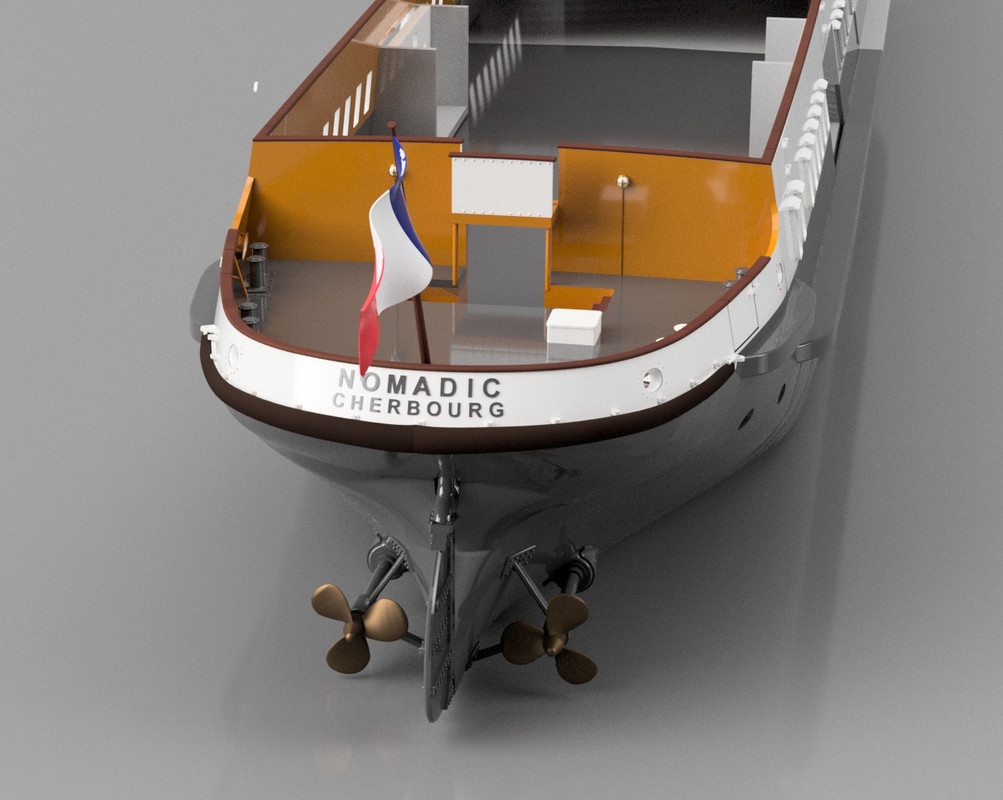
Using the circular "Pattern" function to copy the blade in relation to the shaft line axis.
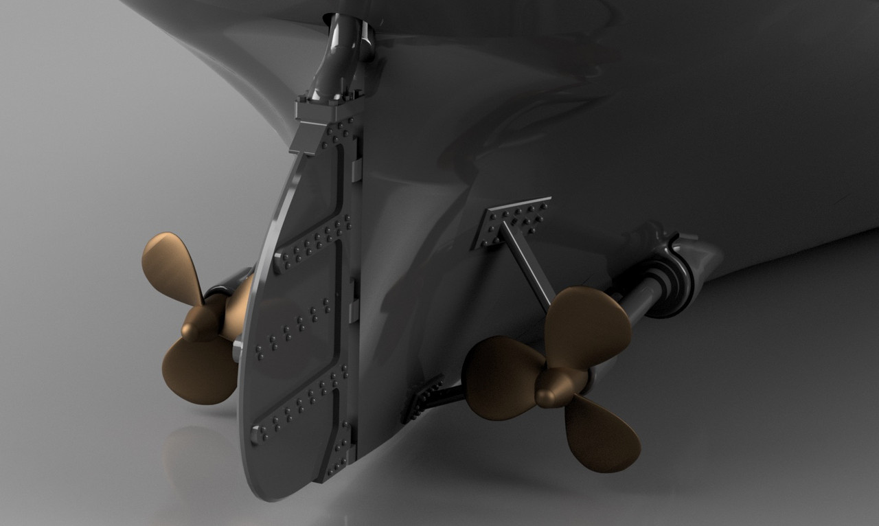
The surface rendering can be further improved by adding 2 rails parallel to the blade axis, but I didn't do it. It's not necessary at this scale, it's very small and just for printing in 3D.