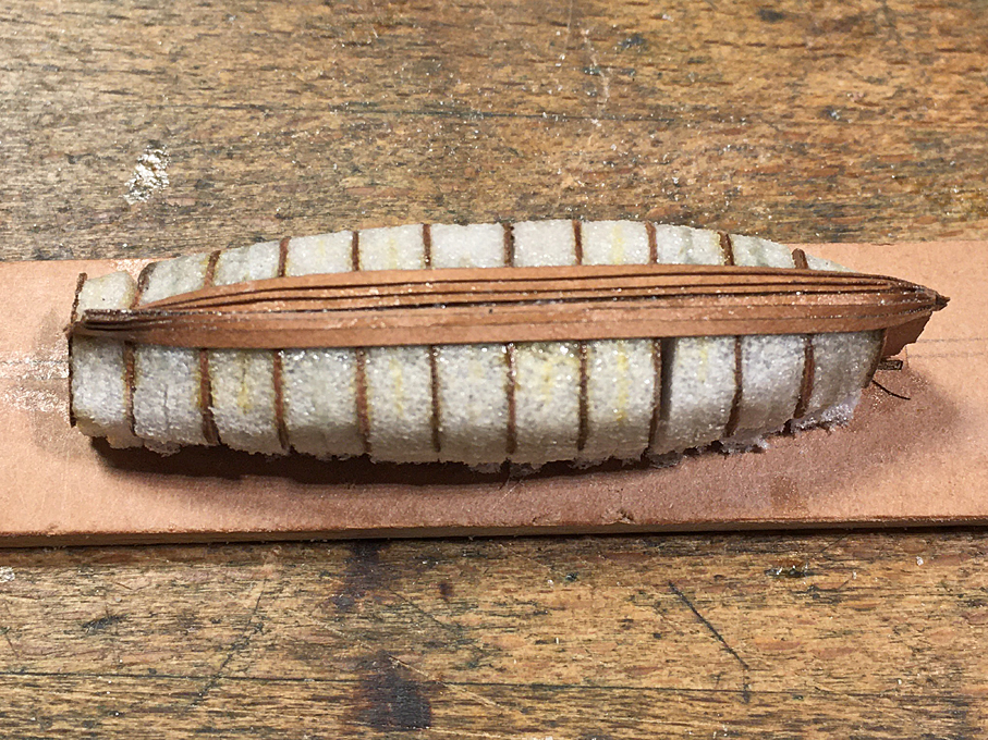
Building fully framed open boatsThe procedure is in principle similar to that of a boat that is covered. However, the bulkheads have to be drawn to the inside of the (bent) frames. The plug is built up in the same way as above. The plug built up from hard foam is then covered in a thin layer of automotive putty, which is carefully sanded down to the laser-cut templates. In order to prevent the structural parts of the boat from sticking to the plug, it is covered in cling-film that is drawn tightly over it, avoiding folds and creases.
This plug is mounted to a baseboard of two layers of paper laminated together with varnish. This baseboard has rectangular holes for holding the bent frames in place, which are cut with the aid of the laser-cutter. The baseboard is glued to a piece of wood that is a bit smaller than the inboard profile of the boat, which allows it to be held in a vice etc. to ease further manipulation.
It is important to remember, that this method of construction only works, if the boat has no tumble-home. Otherwise, it will not be possible to remove the hull from the plug. For boats with tumble-home, one would have to carve a solid former from interlocking pieces that can be released successively and lifted out of the hull.
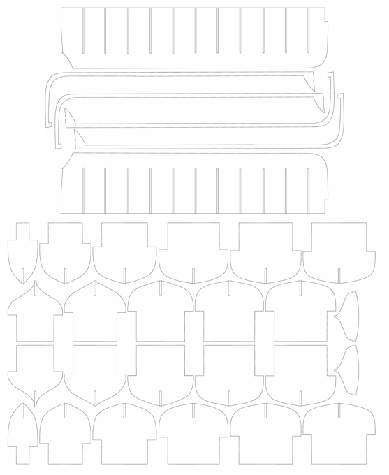
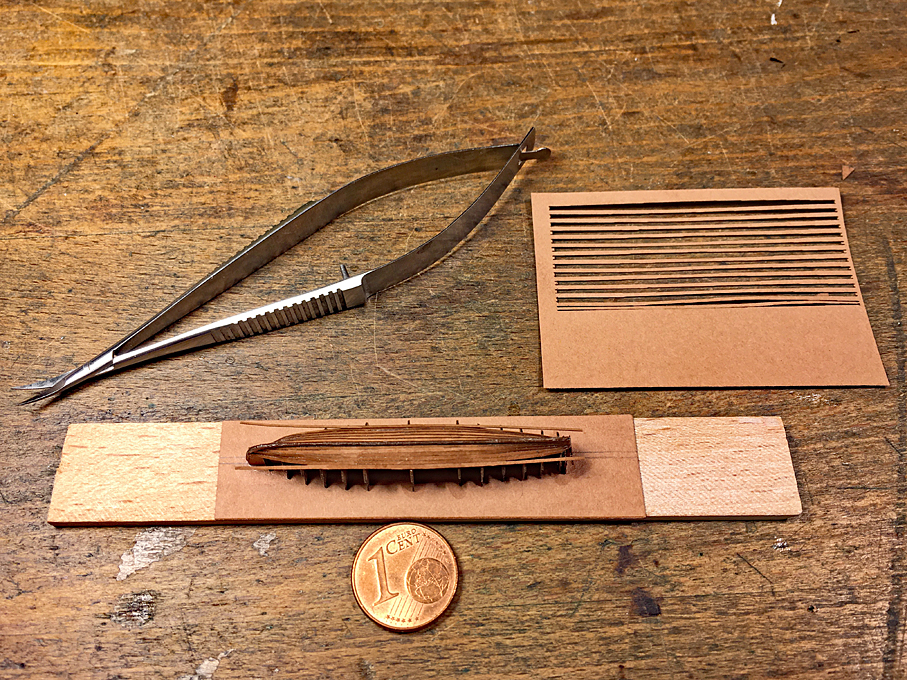
 Laser-cutting templates for the formers and main structural components of a jolly-boat.
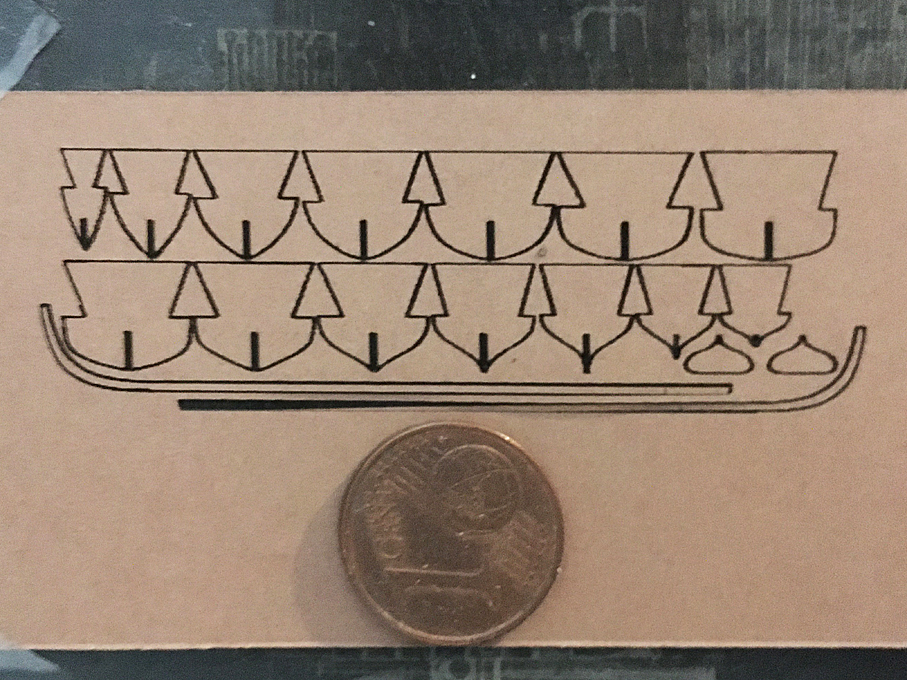
  Plug for the POF construction
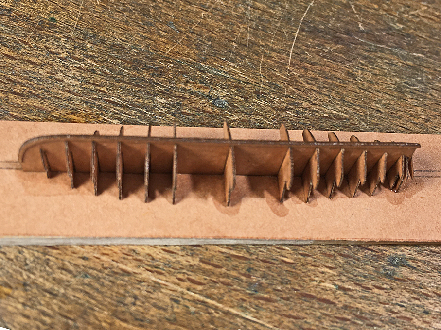
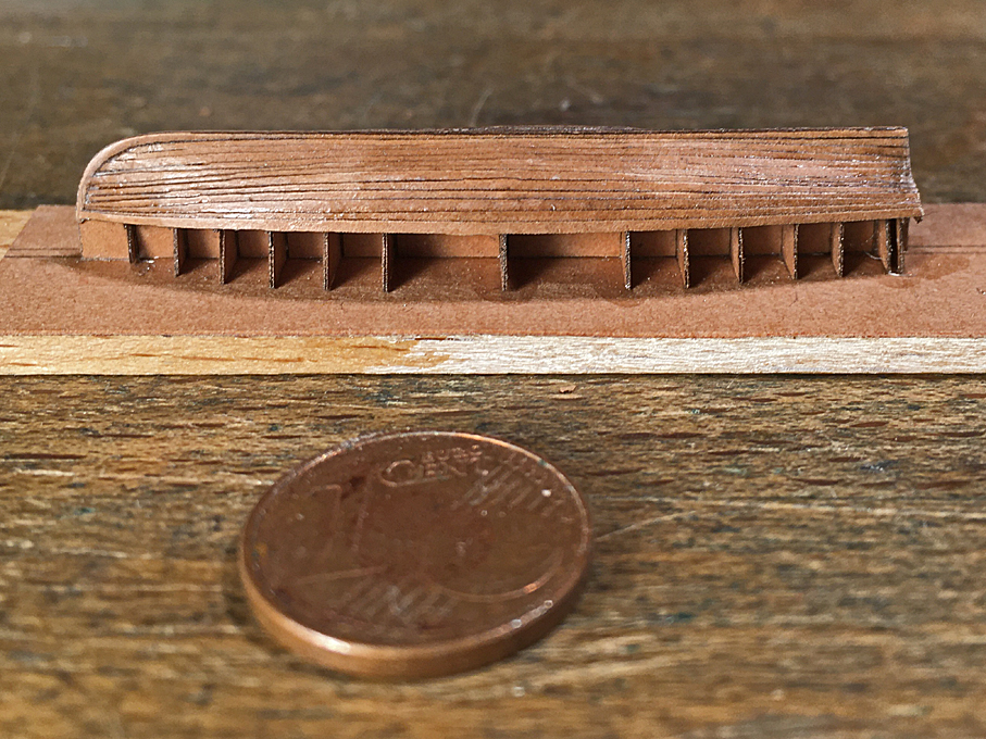
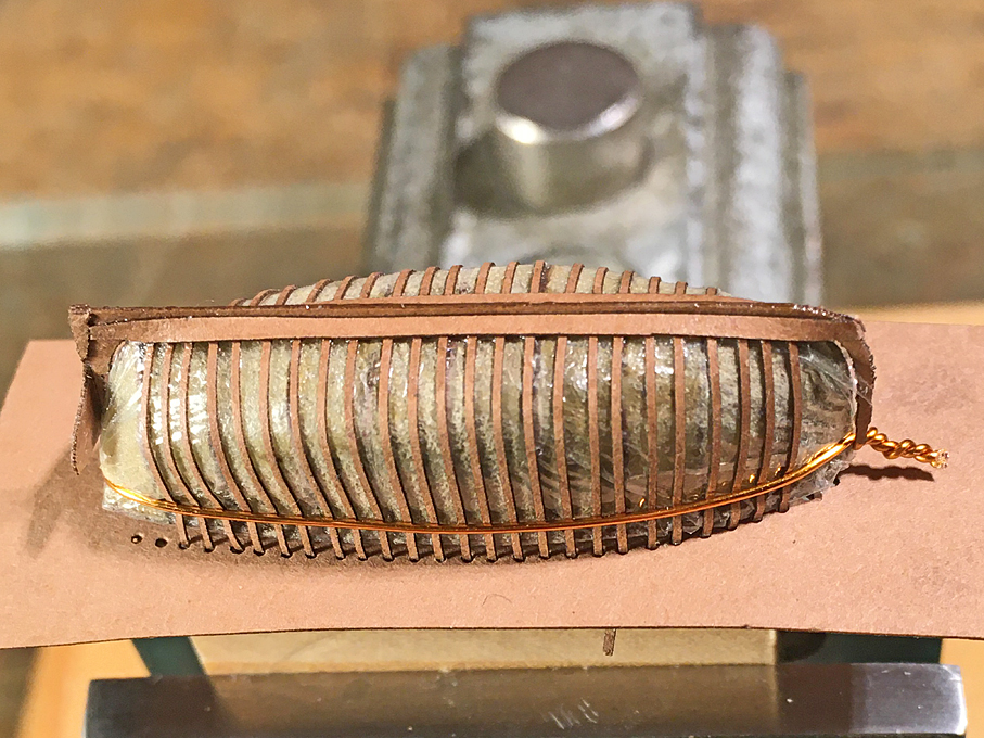
The bent frames are laser-cut strips of paper of the appropriate width. To achieve scale thickness, doubling may be required. The strips are bent around the plug, inserted into the rectangular holes, aligned carefully, and then cemented to the baseboard with varnish. If neede, they can be tied down in addition onto the plug with a length of wire that is tightened by twisting.
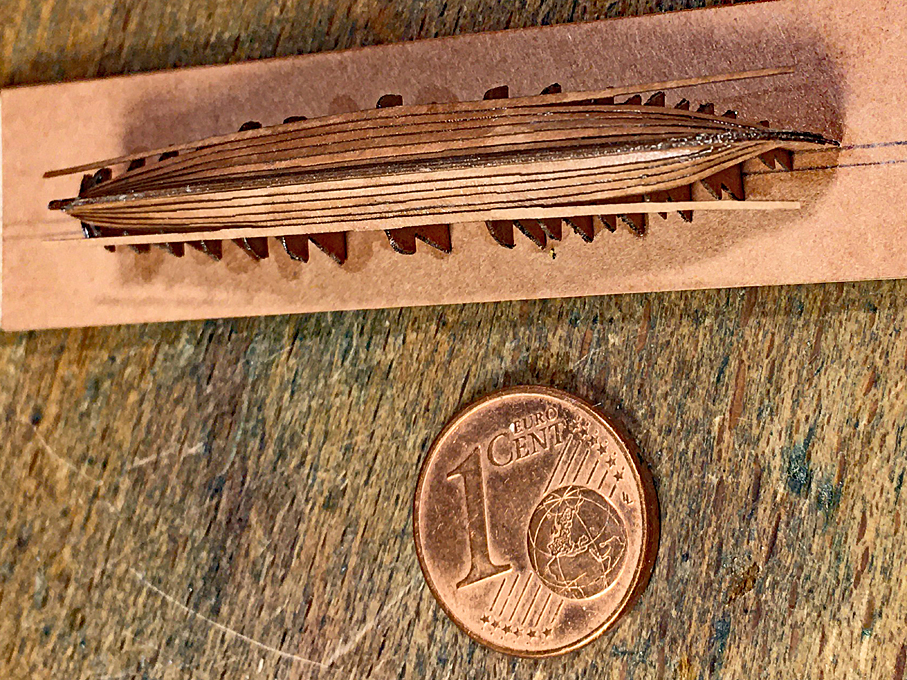
 The backbone of a jolly-boat
The design of the stempost-keel-sternpost part is somewhat different from the previous construction. It is basically in two parts. One part is the part inside the boat and the other part is the one that is visible outside. The separation-line is basically the rabbet-line. The photographs give an idea of this. The actual outboard stempost-keel piece will be added later, after the planking. The interior part will be glued onto the frames now and the transom added.
It should be noted that there will be likely a couple of cant-frames that but against the keel/stem, rather than running under it. In consequence, these can only be installed after the planking of the hull is completed.
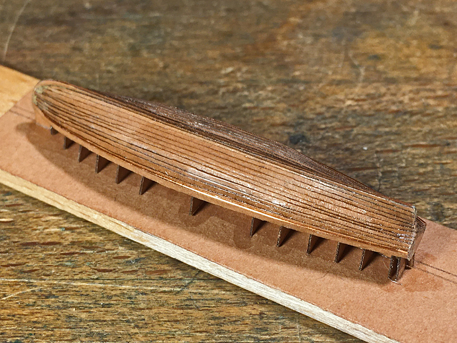
 The framed structure
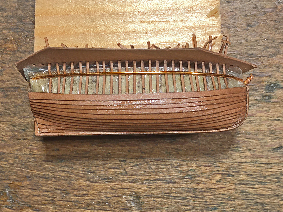
One may have noticed that this is the reverse construction order compared to the full-scale practice. A traditional clinker-built boat would be built over a couple of templates, with the planks going in first and the frames bent in afterwards – the ‘shell-first’ principle. I prefer the described method, because having the frames in place provides more glue surfaces than just the plank edges and thus makes for a stronger shell, when removing it from the plug.
 The garboard-plank installed
I don’t want to hide the fact, the gluing and coercing down the planks here is a bit more difficult than when gluing them to the solid plug. As on any clinker-built boat, the garboard-plank is the most difficult to install due to its torsion and being curved in all planes. Here it is no exception. It needs a fair amount of coercion. Planking, of course, proceeds in parallel on both side of the hull in order to ensure symmetry.
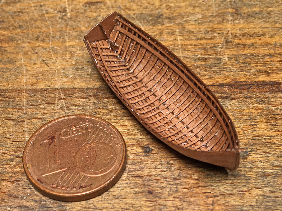
 Planked-up starboard side of a jolly-boat with the stempost-keel-combination also in place
After the planks are on, the outside part of the stempost-keel-combination is installed. With this one cannot really see that is was no real rabbet into which the planks run.
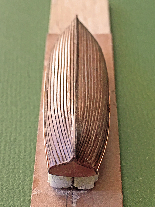
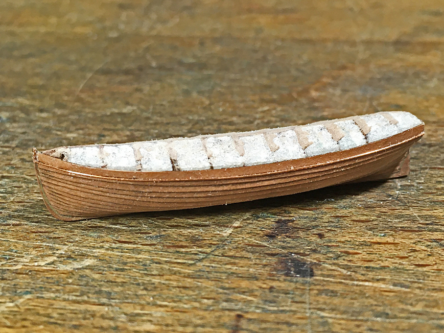
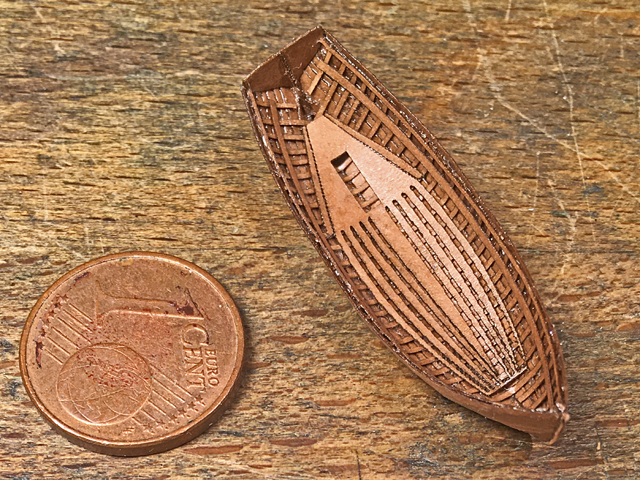
 Looking down onto the planking; the overall length of the boat is 36 mm (just under 1.5")
The next step is to cut the excess length of the bent frames and to cautiously rock the hull in order to release it from the plug. The frames are then trimmed back to the sheer line. If part of the design, the additional (cant)frames will have to go in now, before the further fitting out can begin. The result is a quite strong hull with the typical exterior and interior look of a clinker-built boat.
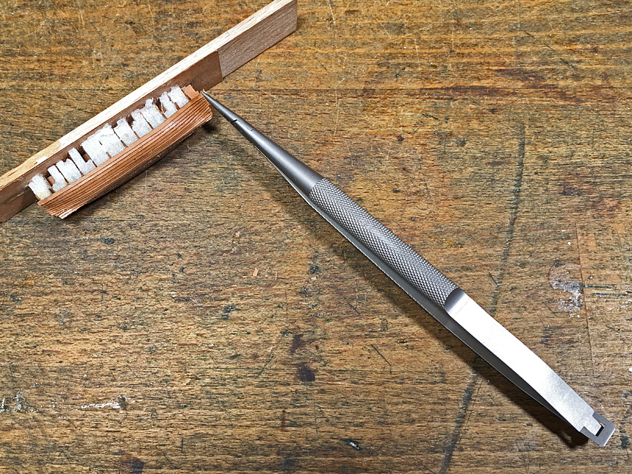
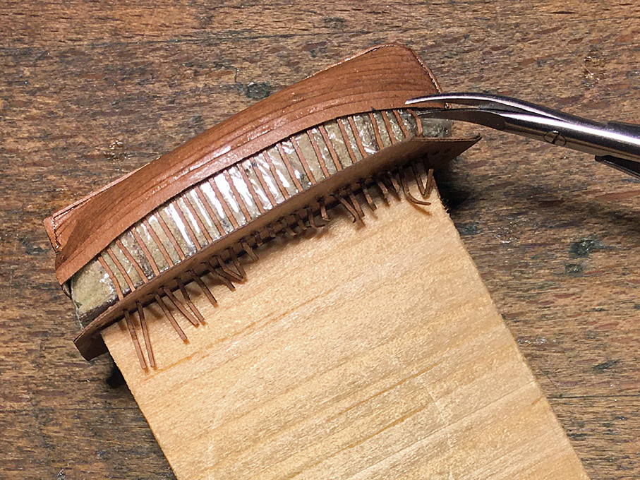 Cutting the extended frames with micro-scissors
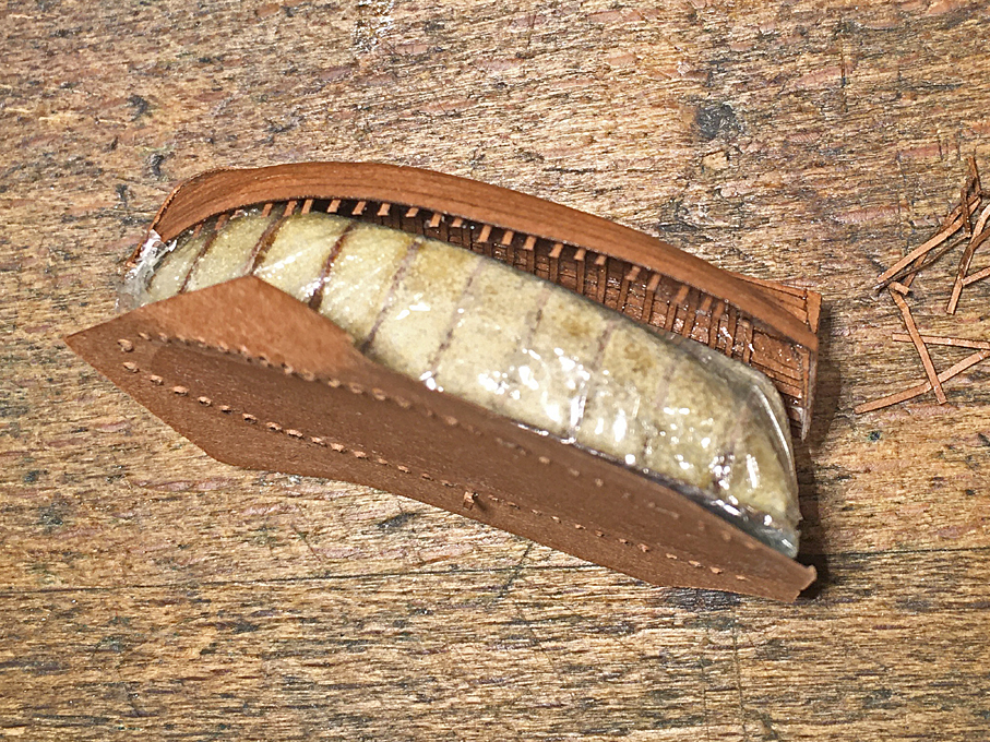 Hull begins to detach from the plug
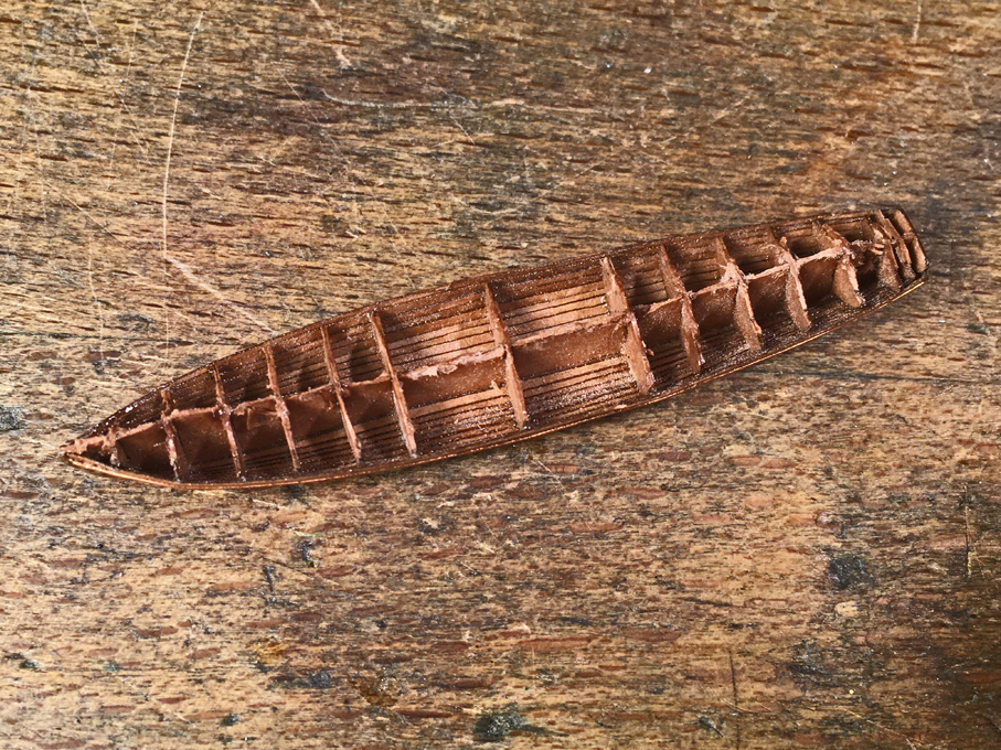
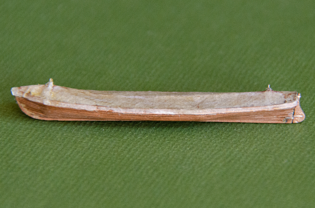
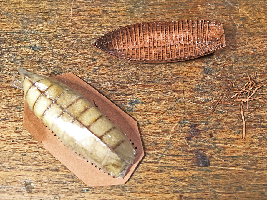 Hull successfully taken off the plug
Next go in the gunwales and the inwales on which the seats rest, all laser-cut strips of paper, doubled where needed and lacquered into place. Now the hull is given a coat of varnish and cautiously rubbed down with steel wool. Any imperfection visible can be touched up with putty, although it is likely, that more become visible once the first coat of paint has been applied to the hull.
 Hull with gunwales and inwales
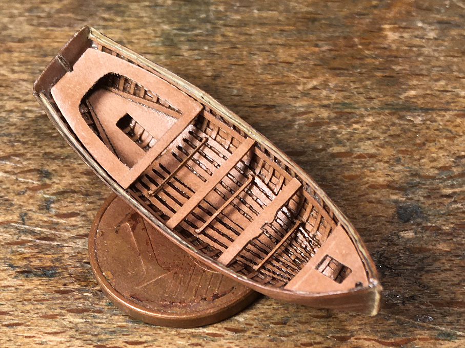
Most open boats have floorboards. These may be arranged in many different ways, but often are panels of several boards, which can be lifted out to give access to the bilge. Aligning these properly can be tricky and it may be a good idea to design them as a single unit, when the joining parts can be hidden under the seats etc.
 Floorboards installed in the hull
At this small scale it is difficult to build precisely to the drawings, so that stern-sheets, seats, and other pieces may not fit exactly as drawn. This requires a bit of trial and error, and perhaps re-drawing for laser-cutting. Still a bit of sanding may be required for a perfect fit.
Sanding paper is not that much fun, but re-soaking it in lacquer after a few strokes with a diamond-file keeps fraying under control.
 Stern-sheets, rowing seats and bow-platform installed
The remaining fitting out depends on the features of the prototype. There may be foot-rests for the rowers, pillars under seats, covering boards over the sheer-strake, strengthening pieces where the thole pins are inserted, reinforcements of the washing-strake around row-locks, mast-steps, etc. All these can be laser-cut pieces. There exact size and shape is best taken off the hull and drawings produced accordingly to control the laser-cutter. They are lacquered into place.
Depending on whether the iron hardware in the boats is going to be painted it can be installed now or left after the main part of painting has been done. The sequence of painting really depends on the kind of prototype.
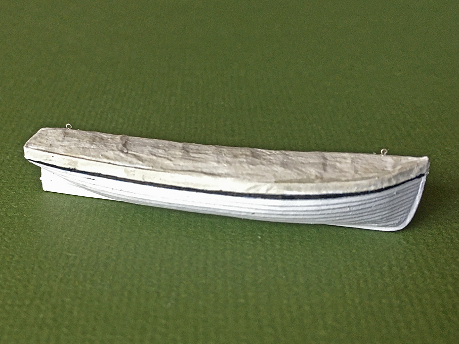
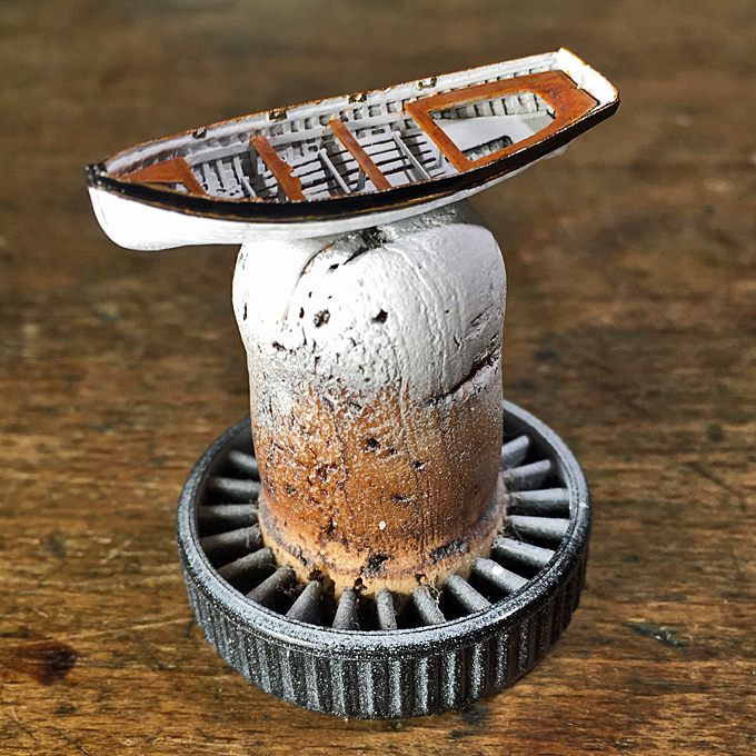 Painted model of a jolly-boat on an ordinary port-wine cork
There will be various items of loose equipment such as the oars, rudders, fenders, a water-cask etc. that also can be produced with the aid of the laser-cutter.
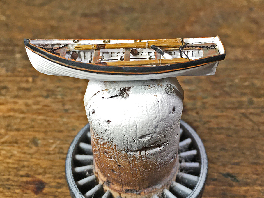 Painted model of a jolly-boat on an ordinary port-wine cork
The oars can also be built up from laser-cut parts. It may need a bit of trial and error to get the right shape and dimensions, as the laser-cutter can be somewhat unpredictable with such small parts. Each oar is lacquered together from three layers to build up their shape. The round of the shaft was built up with more varnish and sanded to shape using a diamond file. More varnish was applied before the paper showed signs of fraying.
 Template for laser-cutting three-part Oars
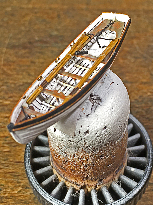 Fully kitted-out jolly-boat in 1/160 scale.
The above lines are only intended to outline the principle of construction. Each boat-type is different and has different elements of construction.
While the description concerned boats with bent frames, the same principle could be used for boats with sawn frames. Again, the plug (if such was used) would need to be moulded to the inside of the now wider frames. Each frame needs to be cut out in multiple copies to build up the necessary thickness. Of course, if one has a stronger laser-cutter, one can use thicker paper/cardboard. The construction then is essentially that of POF and several commercial kits for such boats (albeit at a somewhat larger scale) are already on the market.
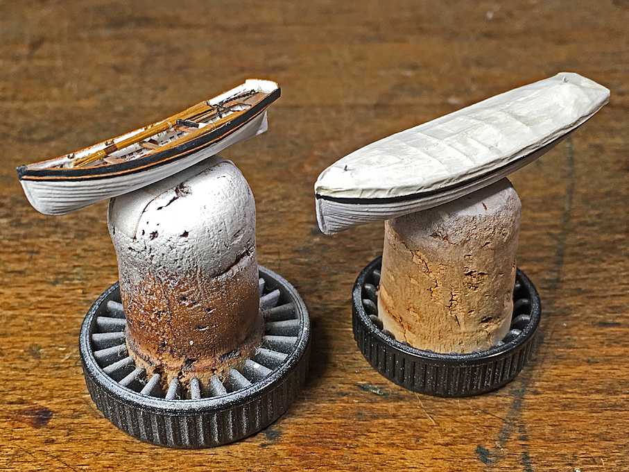 Comparison of a fully frame open and a covered boat in 1/160 scaleTHE END