Sten Ekedahl wrote:
OK, time for a new question: On the drawings in the Stillwell book there appears to be some sort of pipe fitted to the side of the hull, running almost the entire length of the ship. It starts a couple of feet aft of the bow just above the water line, and slowly raises up to the edge of the quarter deck where is seems to end just above the original rearmost 5" casemate gun.
1. What was the purpose of this pipe?
2. Was it present on both sides of the hull? On the side drawing in the book it is shown on the starboard side. But on the photos showing the starboard side (pp. 216, 217) it doesn't seem to be there. OTH, on photos showing the port side (pp. 213, 220-221) it is clearly visible.
TIA
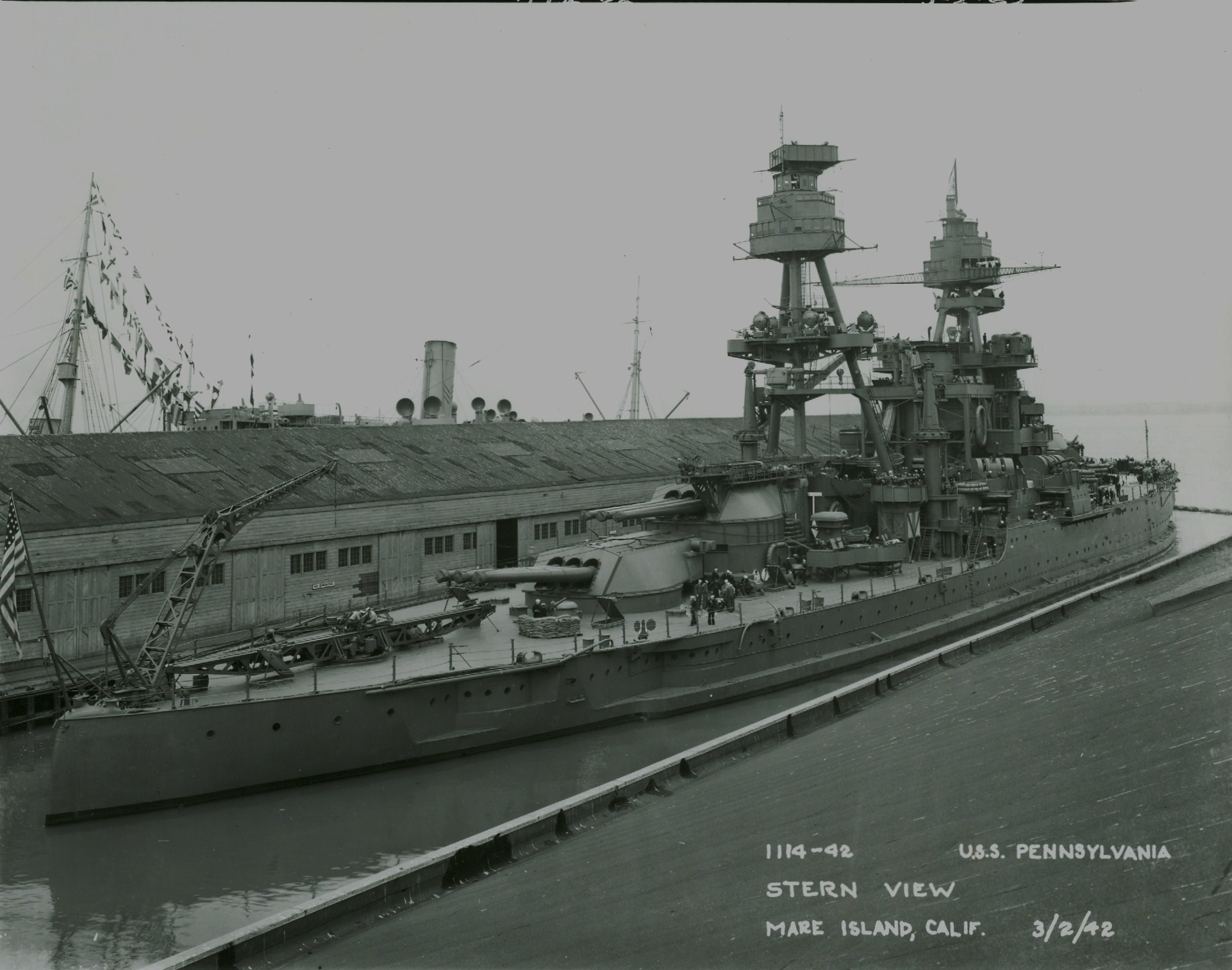
It looks like Pennsylvania had one on her starboard side, similar but not quite the same as the Arizona's port one (Pennsy's runs pretty much level all the way, until making a sharp upward turn. See
http://www.navsource.org/archives/01/013865.jpg for a good phot from early '42. Late '30s photos, though not as close-up, do have a line along this side so this wasn't a post-Pearl addition.) I'm guessing that it's an avgas line, as was seen on lots of U.S. cruisers, and typically on one side only. From the look of things, I suspect both ships got these installed in the late '30s, and only on one side of each.
A couple club-mates and I are group-building Arizonas (One 1/350 Hobby Boss as Arizona 1941, one 1/350 Hobby Boss as Pennsylvania in 1941 fit, and one 1/429 Revell as Arizona 1936 fit), and trying to detail and accurize them as we go along, starting with re-planking the Hobby Boss kits and the mid-ship area of the Revell. Chasing after these little details is both fascinating and frustrating. The new Ray Bean photo CD I picked up at Nationals is a timely and welcome item; for example, the photos on the CD confirm that on Dec. 7, 1941, Pennsylvania did have trusswork yardarms like Arizona and Nevada, and did have her radar mounted. I was previously almost convinced otherwise.
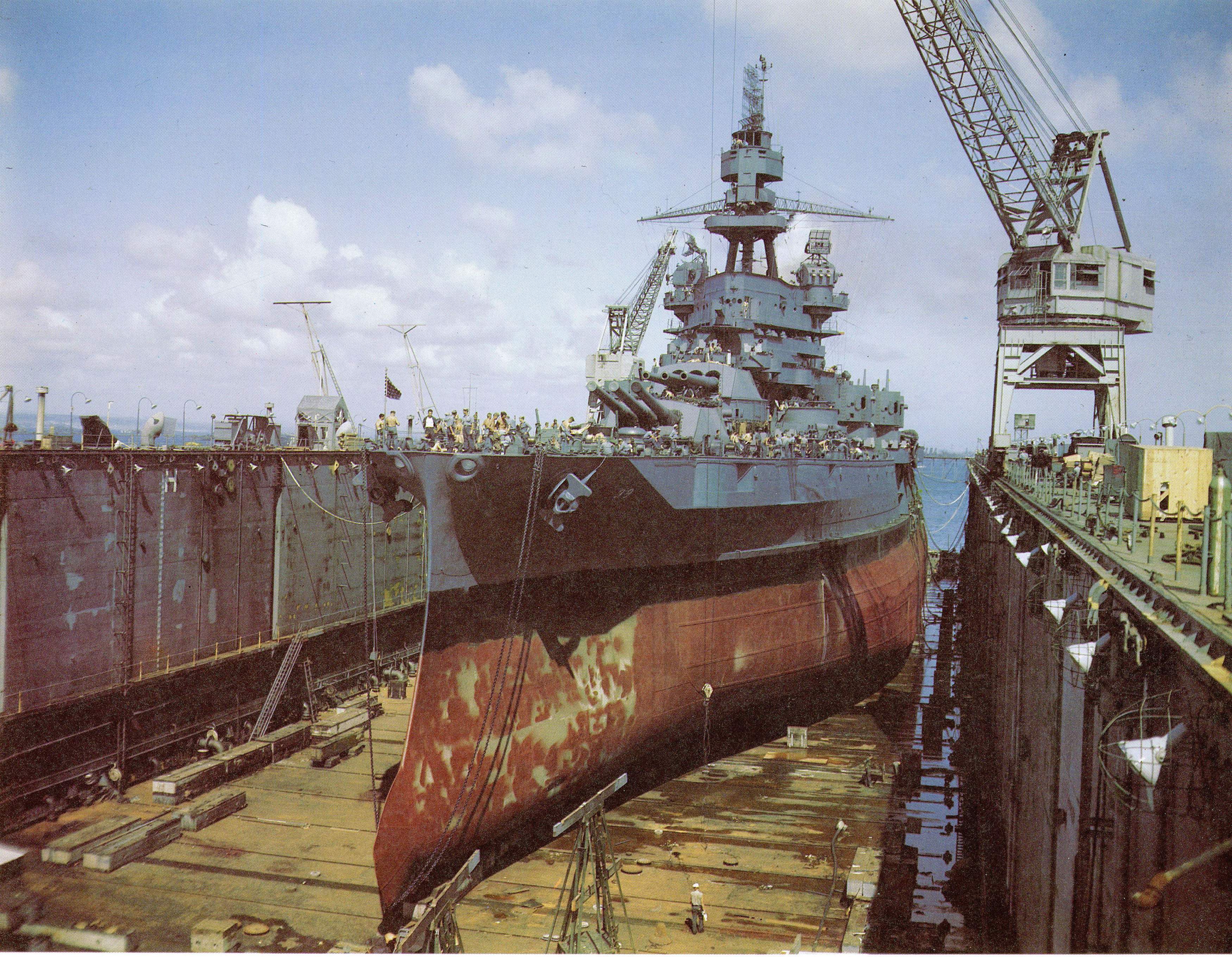
Does anyone know of a good photo or drawing that illustrates the bilge keels and horizntal joints on the bulges (strakes? stiffeners? see
http://www.navsource.org/archives/01/013802.jpg )? The Hobby Boss kit's keels seem a bit too high up the side, and rather thick; and those horizontal lines would make a nice additional detail to have on the hull. (The three I see I'd guess go the full length of the bulges on both sides of the ship; were there more on the bottom?) I have one set of plans from The Floating Drydock, but it doesn't show what I need in this regard; I don't mind buying more plans, but I'd greatly appreciate if anyone could point me to which set I'd need.
- Sean F.


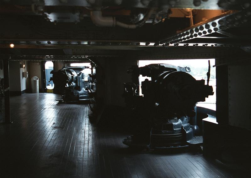
 From looking at various photos I get the impression that bulkheads were painted white or a very light color. But the floors? Green? Can anyone enlighten me?
