The Ship Model Forum

The Ship Modelers Source
It is currently Sun Jan 26, 2025 1:03 am

All times are UTC - 6 hours [ DST ]


Post new topic Reply to topic  [ 2100 posts ]  Go to page Previous  1 ... 70, 71, 72, 73, 74, 75, 76 ... 105  Next
Author Message
PostPosted: Sun Jun 09, 2013 3:34 pm 
Offline

Joined: Thu May 29, 2008 8:02 pm
Posts: 3834
Jamie,

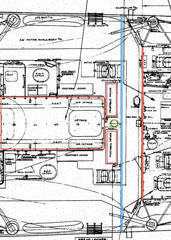
OK I messed things up a bit with my selection of a drawing. The drawing I posted above comes from the Bath Iron Works Engineering drawings for DD-449 through 451, since you are I assume modeling FLETCHER (in 1/700 or 1/350 scale?) out-of-the-box without major mods (true?) this would be as close to the original layout in drawings as I have for her as completed. FLETCHER was built by Federal Shipbuilding to the same plans as BIW, but some minor items could be different. I revised and enlarged the previous drawing to correct some of what I said before and to expand on the discussion. Also, I hunted through my 3,000+ FLETCHER images looking for good views of this area. It isn't easy, because of bulwarks and ships boats this is a difficult area to photograph and most yard photos didn't look at this area as being important for any modifications.


Below - BIW Main Deck layout around the Mast Foundation area; The red lines show where the basic main deck deckhouses are located, midships left and forward right. Between these is a cross ship passageway and the mast is anchored close and in front of the forward bulkhead of the midships deckhouse where the venting uptake and clean air intakes are located. I messed up before in "assuming" that the vegetable lockers were full height (and they may still be, I don't know for sure) and I'm making them outside of the deckhouse. There are lockers in various locations along the main deck midships deckhouse, that are more or less permanent structures of the deckhouse, but some were modified/relocated over time. There is a platform that is part of the 01 deck above part of this "passageway" that sits atop the breakwater bulkhead out to the edge of the ship. I marked the aft most edge of the platform in blue. The mast is circled in green just for completeness. Atop the main deck deckhouse was either one or two "catwalks" on either side of the mast as shown in the small drawing or sometimes on BOTH sides. As a side note, the area marked off with two solid lines passing through the passageway and continues aft on either side of the midships deckhouse, was to indicate where non-skid covering was to be applied ... which actually varied from ship to ship.
Image

01 Deck layout in area around the mast.
Attachment:
DD449-451xMast01Deck.jpg
DD449-451xMast01Deck.jpg [ 90.17 KiB | Viewed 2491 times ]


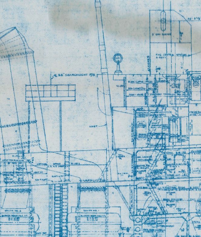
Here is an inboard profile view of the area around the mast area for another Federal-built FLETCHER that shows location and relative orientation of the mast. You can see where the aft end of the forward deckhouse is located and how if they had continued the mast through the deck it would have hit the # 1 boiler!!! This drawing shows the bracing used to transfer the weight of the mast to the bulkhead just forward and in-line with the aft deckhouse bulkhead.
Image


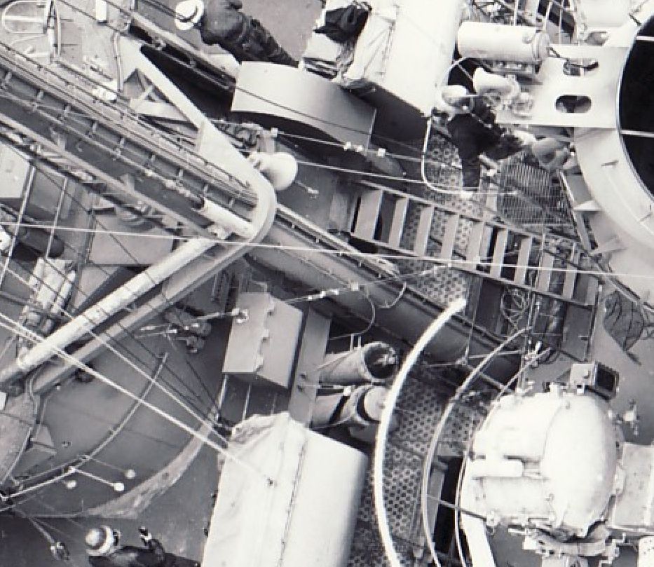
Below are a series of cropped images from various FLETCHERS taken at different periods during WWII. They show that there were catwalks and that the area under the 01 deck platform "extension" at the aft end was "OPEN". Note, that these ships were modified to upgraded configurations and some features were changed/relocated from the original plans. Discussion continued below after the images.

DD-448 LaVALLETTE on 19 July 1943. Note that her catwalk is located on the portside, not on the starboard side as seen in the above drawing. Also, you can see that there isn't a bulkhead at the back edge of the platform.
Image

DD-480 Halford on 15 May 1945.
Image

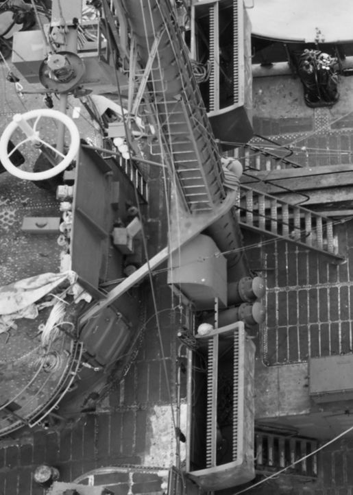
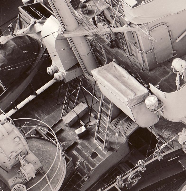
DD-688 REMEY on 11 December 1945. Note that this is about the best view I have showing the open space ... the true cross-deck walkway area ... and that the catwalk is on the starboard side and you can see what look like two likely vegetable lockers on the main deck level on the portside of the mast.
Image


The problem with the TAMIYA FLETCHER kit is that they have placed the aft bulkhead of the forward deckhouse at the back edge of the 01 deck platform ... WRONG!!! Tamiya has the mast more or less in the correct position and there is NO NEED to move it ... but tweaking the location some further aft would be more accurate.

So depending on how you which to proceed, you can ignore this issue and build the kit out of the box since most of the area can't be seen once completed or you can cut out the wrong bulkhead and insert a replacement in the proper location. No need to be fancy about that bulkhead since you can't see much of it. A middle course to consider, since Tamiya uses this wrong placed bulkhead to locate and support the mast and 01 deck, you could cut away much of the area on either side of the mast support structure Tamiya has, but leaving the locator for the mast and assemble the whole thing. Not much can be seen of this area once fulling assembled and the part that can be seen at the outer edges near the sides of the ship would be correct. Or simply remove the whole bulkhead, put in a replacement in the proper location and play with locating the mast (what I have done). The "Aztec" stairs need to be replaced anyway. :smallsmile:

In looking at a Tamiya FLETCHER kit, it has been a longtime since I played with one, there are a lot of details missing in 1/350 scale that could be added to make it a better model. Check the multitude of images in this thread to see missing structural features and equipment (the kit's bridge wings lack any equipment that should be there). Oh ... and the radar seen on the mast is for a SC-2 radar, FLETCHER was completed with the square SC-1 radar antenna.


Top
 Profile  
Reply with quote  
PostPosted: Mon Jun 10, 2013 11:25 pm 
Offline

Joined: Sat Jun 08, 2013 12:17 pm
Posts: 59
Location: BC, Canada
Wow Rick! You outdid yourself! I love your term "Aztec" stairs...exactly what they resemble!
I`m building USS O`Bannon DD-450 from Nov `42 from the 1/350 Tamiya kit, but I think I will leave the mast alone, close enough! I already changed the rear bulhead for the 1 level forward deckhouse as you described.
Do you think DD-450 had the big square SC radar in Nov `42?


Top
 Profile  
Reply with quote  
PostPosted: Tue Jun 11, 2013 2:19 pm 
Offline

Joined: Thu May 29, 2008 8:02 pm
Posts: 3834
Yes, O'BANNON had the SC-1 radar until late in 1943 when she was updated to the five twin 40-mm mounts configuration. I don't know why Tamiya used a SC-2/3 antenna on the FLETCHER kit. I do think that Tamiya "planned" to come out with another or several other versions of the FLETCHER kit, based on how the parts were broken down on sprues.

Remember that NICHOLAS, O'BANNON, and CHEVALIER all had a quad 1.1-in mount instead of a twin 40-mm mount. Quad 1.1-in mounts can be had from aftermarket suppliers or "stealing" one from a DML BENSON/GLEAVES class kit that doesn't need it.

I don't know when O'BANNON received additional 20-mm guns in November 1942 beyond the first six she arrived with. I found references in NICHOLAS' War Diaries to getting one extra 20-mm on 2 November and a second 20-mm on 12 November ... both were installed on the fantail. Eventually NICHOLAS had a ninth 20-mm added (atop the pilothouse) in early December and a tenth sometime later on the fantail when they rearranged the guns on the fantail as well (appears this happened in May 1943). O'BANNON eventually had ten 20-mm guns, but when is unclear. BuOrd records list O'BANNON with ten 20-mm as of 31 March 1943 (but not when they were installed, it took weeks for these records to be updated). O'BANNON and NICHOLAS weren't together in early November time period (NICHOLAS had a broken SG radar, being dispatched to escort a ship back to Noumea and was getting the radar fixed at Noumea, so missed the Battle), and O'BANNON's War Diaries weren't any help, so I don't know when she received extra 20-mm guns. The 20-mm guns, at least on NICHOLAS, were installed by the crew, not a Tender.

You may be safe to assume O'BANNON didn't have extra 20-mm guns added prior to the Battle on 12-13 November. My "gut" says she received her plus-up of 20-mm guns after the Battle when she had some "downtime" at Noumea.

Both units were painted in Ms 21 before the Naval Battle of Guadalcanal.


Top
 Profile  
Reply with quote  
PostPosted: Wed Jun 12, 2013 9:14 am 
Offline
User avatar

Joined: Mon Mar 19, 2012 4:25 am
Posts: 274
I'm about to build the Tamiya kit supplemented by either the GMM, WEM or Eduard detail sets and I plan to paint it in the MS 21 scheme. Two questions:

1. When built out of the box and in the MS 21 scheme can I still use any of the four hull numbers provided (first four ships of the class)? This is intended to be a relaxing project, but I'd prefer not to go too far astray accuracy-wise.
2. Does anyone have any thoughts on the GMM, WEM or Eduard sets? In particular, whether one is more suitable for an early round bridge Fletcher?

Thanks for any help.


Top
 Profile  
Reply with quote  
PostPosted: Wed Jun 12, 2013 11:23 am 
Offline

Joined: Thu May 29, 2008 8:02 pm
Posts: 3834
If you are doing the ship out of the box, there are two options;

1) As completed with one twin 40-mm mount; all four of the units whose hull number decals are included with the kit (DD-445, 446, 447, and 448) will work

2) As upgraded after post-shakedown and prior to going to the Pacific with the kit's optional twin 40-mm mount on the fantail; only three of these were in that configuration, aka DD-445, 447, and 448 with a couple of caveats.

As for painting accurately in Ms 21, the second option is the one that is accurate. If Ms 12mod is desired, the first option is accurate.

Once in the Pacific the three units in the Option 2 configuration;

DD-445 FLETCHER had a single 20-mm added atop the pilothouse on the centerline, not a difficult mod.

DD-447 JENKINS had a centerline elevated platform installed before the bridge for a single 20-mm gun BEFORE she departed for the Pacific and one added atop the pilothouse AFTER arriving in the Pacific. The elevated platform isn't a difficult mod, but if you don't want to go to that trouble then skip this unit.

DD-448 La VALLETTE appears to have been configured like JENKINS or close to it. She was damaged fairly soon after arriving in the Pacific and no "known" photos are available of her after arriving there. Both JENKINS and La VALLETTE were sent on a North Africa convoy support mission prior to heading to the Pacific and had a Yard Availability before leaving for the Pacific. It is known that JENKINS and La VALLETTE had the elevated 20-mm platform installed at New York Navy Yard at that time. Exactly how many 20-mm guns La VALLETTE had when she departed is unknown, they were reduced to four when she had the fantail twin 40-mm mount added in October 1942, as per authorized directions. Whether the waist 20-mm guns on the main deck that had been removed in October were reinstalled as pre "new directions" (one per side) along with the elevated platform gun would mean she had either five or seven 20-mm guns as she departed for the Pacific.

Bottom-line, DD-445 FLETCHER is your safest bet going with option 2 in Ms 21. Adding the 20-mm atop the pilothouse would be a simple addition and would be completely accurate. Have fun with your build!! :wave_1:

PS; Since you are using PE, the air search radar should be the square SC-1 radar, not the rectangular SC-2 that Tamiya put on the foremast.

Note: In this photo the lighter areas on the bulwarks ARE primer, not leftover camo from Ms 12mod. Other photos in the series show that FLETCHER has been/was being "touched-up" during this downtime on 26 March 1943.
Image


Top
 Profile  
Reply with quote  
PostPosted: Thu Jun 13, 2013 8:06 am 
Offline
User avatar

Joined: Mon Mar 19, 2012 4:25 am
Posts: 274
Thanks, Rick. Keeping it to the Fletcher and Ms 21 is about as straightforward as I could ask for. Do you have any photos that show the pilothouse 20mm? If it's something you've posted before I'll just start making my way through the thread pages.


Top
 Profile  
Reply with quote  
PostPosted: Thu Jun 13, 2013 10:40 pm 
Offline

Joined: Sat Jun 08, 2013 12:17 pm
Posts: 59
Location: BC, Canada
Rick: Thanks, I was going to include the extra 20mm on O'Bannon for Nov 42, but now will re-think that due to your comments.

Hey Bill:
Pic I found on the net (or might be one from Rick Davis) of DD-450 O'Bannon with the 20mm on the pilothouse.
I used the GMM set for my 1/350 O'Bannon, its great and includes early, mid & late parts.


Attachments:
1943 jan.jpg
1943 jan.jpg [ 61.36 KiB | Viewed 2278 times ]
Top
 Profile  
Reply with quote  
PostPosted: Fri Jun 14, 2013 1:48 pm 
Offline

Joined: Thu May 29, 2008 8:02 pm
Posts: 3834
Bill,

Sorry I was out of town yesterday.

I don't have the "exact" location of the 20-mm gun atop the pilothouse for units that had it added in the South Pacific. There are no drawings from those installations, as far as I know, since they were done locally. The only overhead views of these 20-mm guns atop the pilothouse roof are on units that had the installation done in a Navy Yard or by a builder. There are no guarantee that the location of the Navy Yard installations are "exactly the same" as the Forward Area installations. Basically, it is known they were installed on the centerline and from photos they appear to be closer to the front of the bridge than the full working circle of the standard mount. This makes sense because it wouldn't be firing aft. I wouldn't be surprised if the "exact" installation locations varied from FLETCHER to FLETCHER class unit.

However saying that and from looking at photos, I think the gun was "likely" located about a working circle arc distance from the front edge of the pilothouse roof, maybe even out to the edge of the pilothouse visor. But since the front/outer edge of the pilothouse roof slopes off this actually provides less than a full working circle around the gun "on the flat section of the roof". An easy way to get at least the rough estimate of the working circle is to reference the circle/arc of the 20-mm gun bulwarks on the 01 deck before the bridge.

Below is a profile view of the centerline 20-mm gun on FLETCHER and a plan view of a Booklet of General Plans drawing for DD-500 RINGGOLD I found at NARA. This drawing shows that they appeared to locate the center of the 20-mm foundation halfway between the Mk 37 director and the front of the pilothouse roof on units that had the gun added while building/fitting-out. Note that the photo of FLETCHER seems to show only one ready service box (on the starboard side), but these are not very clear photos and maybe they are located on this ship aft of the Mk-37 director. Most photos show that a canvas cover was put over the railing and seeing such detail is next to impossible. I think this is as good as we will find out unless a good sharp aerial view surfaces somewhere or a time machine is invented so we can take a tape measure and camera back with us. :big_grin:

Bottom-line kind of wing-it on where to locate the 20-mm gun, they didn't work from drawings when these were first installed ... the crews in the South Pacific "invented" this installation and an official request went up the chain "AFTER" they did it to make this standard on ALL FLETCHERS.


Attachments:
DD445Pilothouse20mm-26Mar43.jpg
DD445Pilothouse20mm-26Mar43.jpg [ 116.33 KiB | Viewed 2254 times ]
DD500Pilothouse20mm-BGP.jpg
DD500Pilothouse20mm-BGP.jpg [ 107.11 KiB | Viewed 2254 times ]
Top
 Profile  
Reply with quote  
PostPosted: Tue Jun 18, 2013 11:34 pm 
Offline

Joined: Sat Jun 08, 2013 12:17 pm
Posts: 59
Location: BC, Canada
Rick do you think DD-450 O'Bannon would have had the surface search SG, BK and TBS antennas on the mast in Nov '42?
Thx


Top
 Profile  
Reply with quote  
PostPosted: Wed Jun 19, 2013 5:51 am 
Offline

Joined: Thu May 29, 2008 8:02 pm
Posts: 3834
SG Surface Search Radar and TBS for sure were installed when complete. The BL "stovepipe" antenna doesn't appear in the earliest photos in the South Pacific, but was there in the summer of 1943. Not sure when it was installed. So I suspect that the BL antenna wasn't aboard in November 1942. The attached image is from O'BANNON's sister, CHEVALIER taken from the rear. I picked this image because it was clearer than any I have for O'BANNON.


Attachments:
DD451Mast-24Oct42.jpg
DD451Mast-24Oct42.jpg [ 10.76 KiB | Viewed 2186 times ]
Top
 Profile  
Reply with quote  
PostPosted: Thu Jun 20, 2013 11:27 pm 
Offline

Joined: Sat Jun 08, 2013 12:17 pm
Posts: 59
Location: BC, Canada
Cool thanks Rick, so the BK was the small round discs installed on either end of the yardarm? Thats how they are depicted in the GMM set.


Top
 Profile  
Reply with quote  
PostPosted: Sat Jun 22, 2013 5:42 am 
Offline

Joined: Thu May 29, 2008 8:02 pm
Posts: 3834
There was only one BK antenna early in the war. The "stovepipe" BL antenna was upgraded to a different antenna that looked similar. TBS was also on the yardarms, but sometimes is hard to see in photos.

The CHEVALIER image above shows a typical DD449-451 installation when they first arrived in the South Pacific. The TBS is the antenna on the port yardarm.

I maybe able to post a better early FLETCHER photo in a couple of days, I'm out-of-town.


Top
 Profile  
Reply with quote  
PostPosted: Fri Jun 28, 2013 11:42 pm 
Offline

Joined: Sat Jun 08, 2013 12:17 pm
Posts: 59
Location: BC, Canada
K Thanks Rick, the GMM PE set supplies 2 BK antennas, one for each end of the yardarm, but I wont install them.


Top
 Profile  
Reply with quote  
PostPosted: Thu Aug 22, 2013 1:35 pm 
Offline

Joined: Wed Dec 24, 2008 6:22 pm
Posts: 35
Gentlemen,

I plan to model the O'Bannon (DD-450) as she took part in the battles of November 1942. I have decided to kit-bash the 1/350 Tamiya and Trumpeter kits. So I will start with some basic questions. This is what I have as far as her configuration of that time -items that I'm not 100% sure:

Radar:

SC-1
BL (IFF)
SG
Mk 4 (for gun director Mk 35)


AA Weapons:

1 quad 1.1 inch (fantail)
6 but perhaps as many as 10 20mm Oerlikon guns
(two before the bridge on 01 level, one atop the pilothouse, two per side on main deck amidships, three on the fantail)
?? .50 cal machine guns (don't know about their positions)

Gun Directors

Mk 51 (don't know exact positions)
Mk 37 (w Mk 4/ Mk 22 radar/antennas)

Camouflage:
MS-21

Could anyone comment and point out omissions, inaccuracies? Sorry if I sound vague but so is my understanding of Fletchers in general.

Pete


Top
 Profile  
Reply with quote  
PostPosted: Thu Aug 22, 2013 2:47 pm 
Offline
Site Admin
Site Admin
User avatar

Joined: Sat Jan 08, 2005 4:31 pm
Posts: 3577
Location: Plattsburg, Missouri
The Tamiya kit and aftermarket fittings are all you really need.

_________________
Timothy Dike
Owner & Administrator
ModelWarships.com


Top
 Profile  
Reply with quote  
PostPosted: Thu Aug 22, 2013 6:13 pm 
Offline

Joined: Thu May 29, 2008 8:02 pm
Posts: 3834
O'BANNON in November 1942, would be pretty much as you list with some unknowns.

Known.

O'BANNON arrived in the South Pacific with the typical five 5-in mounts, one quad 1.1-in mount (in the elevated position between 53 and 54 mounts), and six 20-mm guns (two before the bridge and two per side on the main deck amidships). The radar suite was SC-1, SG, Mk 4, but no BL yet. NO FLETCHER had the Mk 22 radar with the Mk 4 radar (some BENSON-GLEAVES units did in late 1944), the Mk 22 radar was paired with the Mk 12 radar on FLETCHERS. They look nearly the same, but Mk 4 and Mk 12 radars were different. Even when O'BANNON was updated in December 1943 with five twin 40-mm mounts, she didn't get the newer Mk12/22 radar on the Mk 37 director, she retained her Mk 4 radar until converted to a DDE in 1949.

I don't have any images of O'BANNON from November 1942, to firmly know her configuration then, but photos from January 1943 and textual records point to several additions over time.

*** The BL IFF radar wasn't installed in January 1943, so wasn't installed in November 1942.

Unknowns.

*** Four additional 20-mm guns were added to O'BANNON starting in November 1942. But, when and where they were located and even in what order they were initially installed is unknown. I found detailed descriptions for the additional 20-mm guns added to O'BANNON's sister, NICHOLAS, and were installed over a one-two month period (in NICHOLAS case, one in early-November, one late in November, and another in December). But none were added on NICHOLAS until after the November battle and NICHOLAS only got her first one installed when she did because she was at Santos for repairs. By January 1943, O'BANNON had three 20-mm guns added to her fantail and one atop the pilothouse. My guess is that O'BANNON didn't have extra 20-mm guns added at the time of the Battle.

*** I don't know of any 50-cal MGs being added to O'BANNON's armament. I'm pretty sure that the Naval versions of 50-cal MGs were NOT installed. The cooling requirements would have been a major mod and with 20-mm guns being available, that would have been the option of choice. US Army 50-cal MGs "could" have been "procured" and "installed", but I have no photos showing them.

*** Mk 51 director for the quad 1.1-in mount. A question mark. When she departed the East Coast for the Pacific in August 1942, she didn't have any director installed for her quad 1.1-in mount. By January 1943 she had a Mk 51 director installed. When It was installed is unknown. I have not found any records saying when she had hers installed. But, my gut says that installing a director for the quad 1.1-in mount would have been a priority for installation (the wiring was already installed for it) and could have been installed at Santos and I would nod to including it on your build.

*** Camo. When O'BANNON left the East Coast in August 1942, she was likely painted in Ms 18 like her sister NICHOLAS. It is known that the destroyers NOT in Ms 21 in the South Pacific, were ordered to be painted in Ms 21 in late October 1942. Textual records appear to show that O'BANNON was repainted prior to the battle and post battle repair photos show her in Ms 21. So, Ms 21 is the safest camo scheme to use on your model.

Kit-bashing the Tamiya and Trumpeter FLETCHER kits.

I'm not sure what you would gain by kit-bashing the Trumpeter kit with the Tamiya kit. The Tamiya kit is the proper "Round-bridge" unit and the Trumpeter kit is a mid-late war "Square-bridge" unit. Most of what you need is included in the Tamiya kit. Replacement of the 5-in mounts in the Tamiya kit, with nicer after-market mounts would help the build. Trumpeter's 5-in mounts aren't an improvement. Some details like the placement of the K-Gun reload stowage posts could use some tweaking (the kit has them stowed in a straight line, when they should be in a semi-circle around the K-Gun), and other items replaced with PE if desired to go to that level. The Tamiya kit doesn't include a quad 1.1-in mount, so taking a surplus one from a DML BENSON-GLEAVES kit would be an option or getting an after-market mount. Actually, if you are going to "kit-bash" a Tamiya kit with any other kit, a BENSON-GLEAVES kit would be a better option.


Top
 Profile  
Reply with quote  
PostPosted: Fri Aug 23, 2013 4:35 pm 
Offline

Joined: Wed Dec 24, 2008 6:22 pm
Posts: 35
Thank you Rick, very helpful and elaborate response.

What is the location of the Mk 51 director? The pictures I have been able to find are too small to tell.
Would the floater baskets have been the early type? with beams as opposed to perforated / grid type?

Don't know to what level of detail the floating drydock plans are but I plan to purchase the 1942 plans for O'Bannon.

As far as the kit bashing, the Tamiya kit's sheer line is not quite right. The upsweep is almost not curvy at all, whereas the Trumpeter kit has it. This is a subtle detail that would be very difficult to correct.

My other unknown is exactly how the anti-slip panels were laid. I think they would have been continuous, just like Fletcher '42 but not exactly alike, I'm sure.

But thank you, this gets me and my project going.


Top
 Profile  
Reply with quote  
PostPosted: Fri Aug 23, 2013 7:29 pm 
Offline

Joined: Thu May 29, 2008 8:02 pm
Posts: 3834
I have used Trumpeter kits with Tamiya superstructure details for waterline versions of FLETCHERS ... I'm lazy about trying to waterline a Tamiya kit. I really haven't noticed that much difference in shear. Trumpeter kits have other issues that turn me off. Actually I REALLY wish DML would (or someone else) do an all-new tooling FLETCHER in 1/350 scale. All existing kits have accuracy issues and/or age of the tooling.

The Mk 51 was mounted in the director "tub" above and forward of the quad 1.1-in mount. (see attached image)

As for floater net baskets, I don't think O'BANNON had them yet, nor did her early BIW-built/Boston Navy Yard fitted out sisters, NICHOLAS and CHEVALIER. They certainly don't show up in the photos I have of the ships. The original idea of floater nets was to tie them in "bundles" along the deck edge without a "basket". These locations were found to be unacceptable for getting in the way, so the baskets were installed at higher locations aboard the ship. (see attached image) I don't know when they first "installed" floater net "bundles", but the locations seemed to vary over time. In the January 1943 photos (the second image is from one of those) there appear to be bundles aft (about halfway between 55 mount and the prop guards), amidships (as seen below), and one forward (abreast 51 mount). These bundles are hard to spot since they are at the bottom of the side railings. From photos of O'BANNON and her BIW-sisters, NICHOLAS and CHEVALIER, the floater net bundles weren't tied up in the same locations. Now then, the Federal-built units had the wood slats style of floater net baskets installed at New York Navy Yard during fitting-out. So a noticeable different between these two groups.

In the fitting-out photos for O'BANNON, the non-skid surfaces are continuos ... not individual pads. In looking at the fitting out views of FLETCHER and O'BANNON, the patterns for the non-skid seem pretty close. Many features for the first built FLETCHERS at BIW and Federal, were nearly identical ... they were building to the original Gibbs and Cox plans. But, it didn't take long for differences to crop up as authorized changes rapidly altered the ships configuration and variations by the builders/yards appeared.

I don't know about the Floating Drydock plans for O'BANNON as to how detailed they are. The BIW Engineering Drawings DVD from DestroyerHistory.Org have the original as "delivered" drawings for O'BANNON and her sisters built at BIW ... http://destroyerhistory.org/destroyers/store/ ... changes done by the Navy Yards or in the South Pacific didn't get recorded on these drawings.


Attachments:
DD450xaftdeckhouse.jpg
DD450xaftdeckhouse.jpg [ 106.98 KiB | Viewed 2408 times ]
DD450amidships.jpg
DD450amidships.jpg [ 108.01 KiB | Viewed 2408 times ]
Top
 Profile  
Reply with quote  
PostPosted: Mon Aug 26, 2013 10:32 am 
Offline

Joined: Tue Jul 10, 2012 2:56 pm
Posts: 78
I have quite a few photos of USS Laffey (museum ship in Charleston, S.C.). Let me know if you need anything in particular.

Image

Rob


Top
 Profile  
Reply with quote  
PostPosted: Mon Aug 26, 2013 10:45 am 
Offline

Joined: Thu May 29, 2008 8:02 pm
Posts: 3834
Nice photos and would be useful for someone building a model of USS LAFFEY or one of her sisters.

But, LAFFEY is a SUMNER class destroyer, not a FLETCHER class destroyer.

I suggest reposting under the Calling all SUMNER/GEARING class Fans thread ... viewtopic.php?f=49&t=21795 ...


Top
 Profile  
Reply with quote  
Display posts from previous:  Sort by  
Post new topic Reply to topic  [ 2100 posts ]  Go to page Previous  1 ... 70, 71, 72, 73, 74, 75, 76 ... 105  Next

All times are UTC - 6 hours [ DST ]


Who is online

Users browsing this forum: No registered users and 23 guests


You can post new topics in this forum
You can reply to topics in this forum
You cannot edit your posts in this forum
You cannot delete your posts in this forum
You cannot post attachments in this forum

Jump to:  
Powered by phpBB® Forum Software © phpBB Group