Mike Sills,
Impressive effort. Keep us updated. Is that the 1/350 or 1/700 version? I filled my filled 1/350 hull entrirely with resin in stages and I have been giving it time to cure. The hangar deck, fantail and forecastle deck pieces are installed. I hope I can pull off a full hull as well as your waterline seems to be coming along. I anticipate that the end result will be a solid resin hull merging into the kit hangar deck and forecastle. You do not understate the Trumpy inaccuracies! There are a lot more in error above deck as well, but a lot easier to fix.
Mike Vorrasi
Calling all USS Hornet CV-8 fans
Moderators: BB62vet, MartinJQuinn, Timmy C, Gernot, Olaf Held, Dan K, HMAS, ModelMonkey
-
Michael Vorrasi

- Posts: 476
- Joined: Sun May 08, 2005 11:15 am
- Location: Brooklyn NY USA
John and guest poster,Anonymous wrote:John,So, OK. Here's another question: what is the purpose of the pair of probably tubular arms projecting horizontally and athwartships on the port side of HORNET, midships? They appear to be maybe 30' long, and they have a support rod to keep the horizontal arm, well, horizontal. They show in both the pictures of HORNET driving through the heavy seas just prior to Doolittle's launch, and they are quite apparent on closeups of the ship being abandoned at Santa Cruz. They look like a supporting structure for horizontal antenna wires, maybe 70' long and parallel to the ship's centerline. I assume they could be HF antennae, but I don't see anything clearly strung between the arms. I don't recall seeing any pictures of ENT or YKTN with a similar fitting. Any thoughts? /
I looked at photo 02/020816 on NavSource to check the locations, and then went to the Maryland Silver plan book. The drawings on page 45 and 46 show what appears to be these fittings. Page 34 has a notation for "emergency antenna outrigger" at the forward of the two stations.
I would be only guessing, but it lends weight to your supposition. Anybody know for sure?
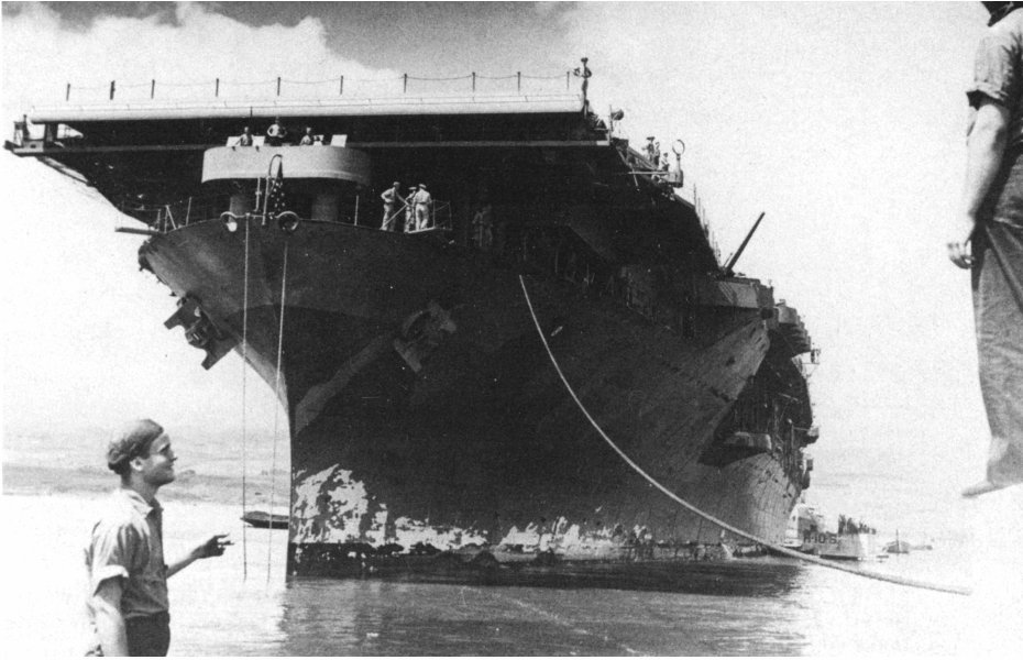
I believe these are swing out structures to support HF wire antenna, similar to the fold down antenna towers that are seen on Essexes in various number along their starboard flight decks. CV5,6 and 8 had several HF wire antennas stung between their tripod and main masts, and CV8 had these additional HF retractable support stuctures along the port side which appear to be unique to her. Hornet also had a foldout DF Loop antenna of impressive size that folded under the port forward corner of her flight deck. It is visible extended in the photo of Hornet at Pearl looking up at her bow with a sailor pointing at her beat up paint work from the shore, and you can see it in the folded stowed position in the attached Santa Cruz abandon ship photo, inboard of the catwalk.
http://www.navsource.org/archives/02/08.htm (Moderator note: Scroll down til you get to photo NS020827)

Mike

-
Cadman

- Site Admin

- Posts: 3631
- Joined: Sat Jan 08, 2005 4:31 pm
- Location: Plattsburg, Missouri
You might find this old feature on the BWN and Trumpeter Hornet by Michael Vorrasi and Jeff Herne helpful.
-
Mike Sills
(I was the inadvertant anonymous author on the post about the antenna outriggers. My bad.)
Mike Vorrasi,
The model is 1/350. I'm interested in the various techniques that different builders have used to try to fix this thing. I heard from one individual who grafted on part of a 1/400 Heller ship hull (I forget which kit he used). Your full hull sounds ambitious, I shudder at the thought of all that resin dust
I've you to thank for much of the research and guidance that has led me so far. You tipped me off to the Maryland Silver books and the usefulness of the Revell hull as a resource. That has had unintended consequences! (I posted pix to the CV-5 page)
I'm starting to get to the point where the flight deck will be added, and this is raising some question in my mind as to how the catwalks should be structurally attached. The kit has solid plastic vertical bulwarks beneath the flight deck, but pictures seem to show this area to be more recessed on the actual ship, with vertical "brackets" that the catwalks are hung from. Is this correct? The MS plan book isn't very clear on this, the appropriate drawings are cluttered with a depiction of the safety nets and railing.
-
david sewell
- Posts: 4
- Joined: Sat Jan 22, 2005 6:59 pm
- Location: Houston, Tx
-
John W.

- Posts: 518
- Joined: Tue Mar 27, 2007 12:34 pm
- Location: Smithfield, Virginia
Catwalks
Mike Sills -
The question you ask about the catwalks bedeviled me for a long time. I studied plenty of (grainy) photos and looked at plans till I was Blue in the face. Trumpeter's kit shows a flight deck overhang where the port forward 20 MM (on HORNET) are located, that doesn't agree with the plans for example.
My solution, unexpectedly, came form Chesneau's book - at least indirectly. There's a picture in that book of the CV-5 builder's model. The caption suggested it was close to where I live. It is, in fact, on public display at the Virginia Air and Space Center, Hampton, VA. It was built in the '30s and does not have the superdetail level we would expect of more moder models. But it is sixteen feet long, and has sufficient detail to show what you are looking for. The catwalk areas are, indeed, fairly complex. In the area where Trumpeter has the flight deck overhang above the 20 MM mounts discussed above, there are actually shelter areas where the gun crews could escape the weather and/or splinters. The inner edge of the catwalk is aligned with the flight deck edge, not inset toward the ship centerline. That overhang on the kit is a structure made up of plating and entry points (not hatches). The plans show this once one knows what one is looking for.
The model shows YORKTOWN in her as-built configuration as near as I can tell. Not sure where you may live, but seeing the model would help greatly by providing some isometric perspective plans do not have. I do not yet have the Maryland Silver HORNET plans book Mike Vorassi talks bout, so I cannot say if it helps more than other sources I have.
-
Mike Sills
John W
Thank you. I know exactly what you mean by the advantage of a 3-D reference. I'm up in the Chicago area, but I get around the country a lot. Any idea how far the model would be from Dulles or the DC area?
Mike Vorrasi- yet another question! You wrote:
Thank you. I know exactly what you mean by the advantage of a 3-D reference. I'm up in the Chicago area, but I get around the country a lot. Any idea how far the model would be from Dulles or the DC area?
Mike Vorrasi- yet another question! You wrote:
I've been working on the island mods (offset pilot house, etc) The kit's flag platform is not symmetrical, but angles inward on the port side. None of the drawings I have depict this. Was it a mod or is it Trumpy's error?Several island platforms were modified by 2/42/
-
John W.
- Posts: 518
- Joined: Tue Mar 27, 2007 12:34 pm
- Location: Smithfield, Virginia
Catwalk locations.
Mike S -
From Dulles or DC, get to I-95 South, then take I-95 S to Richmond, Take I-295 around East of Richmond, then I-64 South toward Norfolk. You reach Hampton just before I-64 goes through the Hampton Roads Bridge Tunnel (this is NOT the Chesapeake Bay BT) to Norfolk. I have covered that distance in two and a half hours, maybe three if you poke along at 55 (not easy to do 55 on I-64 or I-95) as long as you stay away from peak traffic hours.
PM me for more details if you wish.
-
Michael Vorrasi
- Posts: 476
- Joined: Sun May 08, 2005 11:15 am
- Location: Brooklyn NY USA
Actually Mike, it is one of the few things that Trumpy got right sort of, thanks to me by the way! The flag bridge was cut back on an angle to permit a better view towards the landing area of the flight deck. Same was done to prifly. Trumpy did not get the dimensions exactly right though. Both corners of the flag bridge should be equi-distant from the island center line. The port side was angled back and curved into the island. It was done in 01/42 yard period and does not appear in any plan set, but photos show it clearly. Try this Navsource photo. (They can't be hotlinked to appear here, so just click on the link. You may have to go to the site if it flops. They are annoying!)Mike Sills wrote:John W
Thank you. I know exactly what you mean by the advantage of a 3-D reference. I'm up in the Chicago area, but I get around the country a lot. Any idea how far the model would be from Dulles or the DC area?
Mike Vorrasi- yet another question! You wrote:
I've been working on the island mods (offset pilot house, etc) The kit's flag platform is not symmetrical, but angles inward on the port side. None of the drawings I have depict this. Was it a mod or is it Trumpy's error?Several island platforms were modified by 2/42/
http://www.navsource.org/archives/02/020831.jpg
and this one, look just above the loadspeaker here:

Mike
-
Michael Vorrasi
- Posts: 476
- Joined: Sun May 08, 2005 11:15 am
- Location: Brooklyn NY USA
More on the retractable emergency antenna supports. I now can now say these were not unique to CV-8. CV-5 and 6 also had them. I just found a prewar Enterprise photo from 1940 on Page 138 of USS Enterprise (CV-6) by Steve Ewing (Pictorial Histories)and she has 2 antenna masts rigged out. Also, on page 60, post 10/43 refit, she also has 2 of them rigged out. CV-5 shows them at Midway in photo on page 36, and she too has two of these clearly visible. CV-8 however, appears to have had three of them to Yorktown and Enterprise's pair each. There appears to be several antenna wires running between them.Michael Vorrasi wrote:John and guest poster,Anonymous wrote: John,
I looked at photo 02/020816 on NavSource to check the locations, and then went to the Maryland Silver plan book. The drawings on page 45 and 46 show what appears to be these fittings. Page 34 has a notation for "emergency antenna outrigger" at the forward of the two stations.
I would be only guessing, but it lends weight to your supposition. Anybody know for sure?
I believe these are swing out structures to support HF wire antenna, similar to the fold down antenna towers that are seen on Essexes in various number along their starboard flight decks. CV5,6 and 8 had several HF wire antennas stung between their tripod and main masts, and CV8 had these additional HF retractable support stuctures along the port side which appear to be unique to her. Hornet also had a foldout DF Loop antenna of impressive size that folded under the port forward corner of her flight deck. It is visible extended in the photo of Hornet at Pearl looking up at her bow with a sailor pointing at her beat up paint work from the shore, and you can see it in the folded stowed position in the attached Santa Cruz abandon ship photo, inboard of the catwalk.
http://www.navsource.org/archives/02/020827.jpg
(Look at the two horizontal masts with the angled support arms on Yorktown's port side. don't mix up with booms and lines being used to abandon ship.)

Also, see them showing clearly on CV-6 in the third photo down in the 1940 year at http://www.CV-6.orghttp://www.cv6.org/noumea/default.asp?u ... /date/1940
Mike
-
Michael Vorrasi
- Posts: 476
- Joined: Sun May 08, 2005 11:15 am
- Location: Brooklyn NY USA
Emergency radio masts
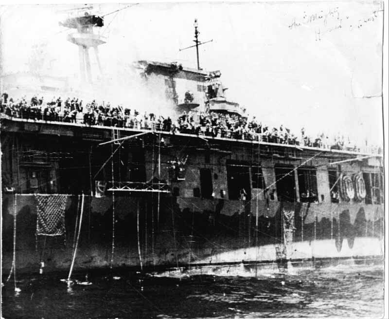
This shot of Hornet at Santa Cruz shows two of the emergency antenna masts clearly. Notice the 2 brackets, one at the end and one a bit closer in, with at least three insulators on each bracket, indicating antenna wires strung out between them (The wires are too fine to be visible, but the insulators are the dead givaway).
Mike
-
Mike Sills
Island Changes
My 1/350 Trumpeter Hornet build has me back on the chain gang and hard at work. I�ve spent the last week rebuilding the island. This was tougher than it should have been because I had started it two years ago, without good plans and mercifully blessed with ignorance. With the MS plan book and all the photos I could muster for references, I tore everything apart and corrected all the platforms, pilot house, and pri-fly. Lots of challenges, but I�m pretty happy with the results and hope to have pix posted in a day or so.
Still trying to get a handle on some of the 1942 changes:
1) Raised searchlight platforms (parts F20) were superimposed on the ex-.50 cal platforms that were abeam the foremast. Were these centered on the lower platforms? From photos, it looks like they may be mounted a little outboard, but my eye may be fooling me.
2) Just aft of these, there is splinter shielding for walkways around the aft legs of the tripod. Outboard, this connects back to the signal flag stowage. Inboard, does it extend all the way across, or are there two separate sections?
3) Mike V. says that the walkway around the funnel top was removed prior to Santa Cruz. From photos it appears that a small section of it was retained on the aft end of the stack beneath the mast. Was this so?
4) Anybody have a photo, drawing, or idea as to what equipment and fittings should be in the rebuilt foretop platforms?
Thanks!
-
Michael Vorrasi
- Posts: 476
- Joined: Sun May 08, 2005 11:15 am
- Location: Brooklyn NY USA
Re: Island Changes
Mike Sills wrote:My 1/350 Trumpeter Hornet build has me back on the chain gang and hard at work. I�ve spent the last week rebuilding the island. This was tougher than it should have been because I had started it two years ago, without good plans and mercifully blessed with ignorance. With the MS plan book and all the photos I could muster for references, I tore everything apart and corrected all the platforms, pilot house, and pri-fly. Lots of challenges, but I�m pretty happy with the results and hope to have pix posted in a day or so.
Still trying to get a handle on some of the 1942 changes:
1) Raised searchlight platforms (parts F20) were superimposed on the ex-.50 cal platforms that were abeam the foremast. Were these centered on the lower platforms? From photos, it looks like they may be mounted a little outboard, but my eye may be fooling me.
2) Just aft of these, there is splinter shielding for walkways around the aft legs of the tripod. Outboard, this connects back to the signal flag stowage. Inboard, does it extend all the way across, or are there two separate sections?
3) Mike V. says that the walkway around the funnel top was removed prior to Santa Cruz. From photos it appears that a small section of it was retained on the aft end of the stack beneath the mast. Was this so?
4) Anybody have a photo, drawing, or idea as to what equipment and fittings should be in the rebuilt foretop platforms?
Thanks!
Mike,
Here goes!
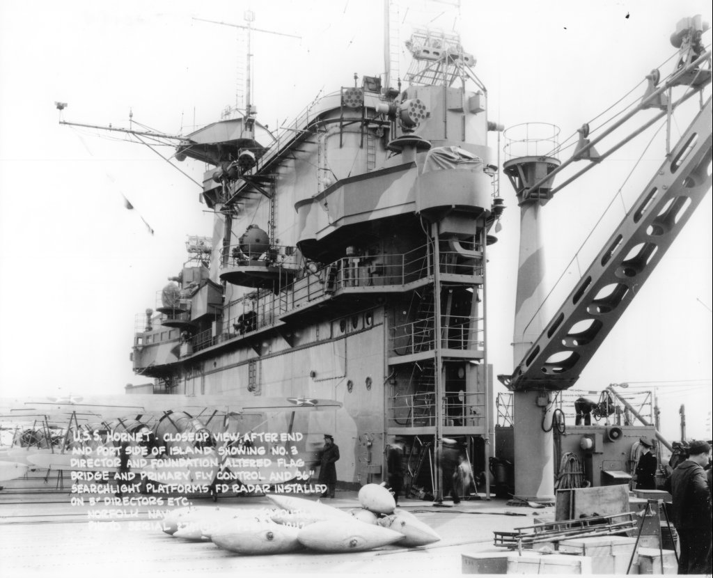
1. I am not sure those platforms were ever used as intended, as .50 cal. platforms, at least not on Hornet (although designed as such) The searchlights were indeed mounted outboard of the center point of the underlying platform, no doubt to improve arcs fore and aft. Note that PriFly as modified in Jan 1942, ended directly under the center of the port platform. PriFly's forward face was perpendicular to the ship's fore-aft axis (not angled as Trumpy did it), and there was a stairway from PriFly's roof down to the navigation bridge, which is much wider than the kit depicts, all to port, along with the wider pilot house, also extending to port. (See famous photos of Capt. Mitscher standing here watching Doolittle's takeoff. The railings (covered with canvas wind dodgers) show PriFly's true shape.)
2. The splinter shield you refer to is visible in the famous Santa Cruz battle flag photo. It isn't really a splinter shield. It is a windshield for the signal bridge, and it appears on her plans. It goes all the way across, with a swinging door located just starboard of the midway point.
3. Good point! The full length walkway was removed after Midway, but a piece was left wrapping around the aft end of the funnel for access to the mainmast and area around the rear of the funnel, as there was considerable equipment up there that needed servicing, mainly loudspeakers and the SC antenna, moved to the mainmast when the CXAM was installed on the tripod top platform, plus numerous small items (electronics and navigation) mounted on her beefed up main mast.
4. The top one, prior to Midway, had the SC antenna and mounting gear, after Midway, CXAM took its place, with SC moving aft. The top platform would be clear of most things as the big radar antenna needed a clear arc to turn in. Top platform- SC/CXAM mounting, and two big drum like loudspeakers on the front edge. Her lower platform does not look to have any equipment mounted after Midway. Prior to Midway, there was a small antenna mounted on a pedestal that looks a lot like a Mk 4 20MM gun mount pedestal. Dick J. (who is expert in electronics warfare) and I have been trying to make sense of this and a couple of other obscure antenna she mounted above her pilot house. Maybe IFF gear or something like it. Are you aware of the weight reduction cuts made to Hornet's lower tripod platform in her Jan 1942 yard post shakedown refit? I have a drawing showing what sections were cut away if you need it, but just study her platform in photos with original Meas. 12 with those taken after she appeared in Meas 12 mod, and you will see what was cut - basically, the tail end, and two sections from the 10 and 2 o'clock positions were shaved off. If memory serves, Trumpy actually got this one right.
Mike Vorrasi
Mike
-
Mike Sills
- Posts: 22
- Joined: Wed Apr 18, 2007 8:47 am
- Location: St. Charles, IL
HORNET Island Build
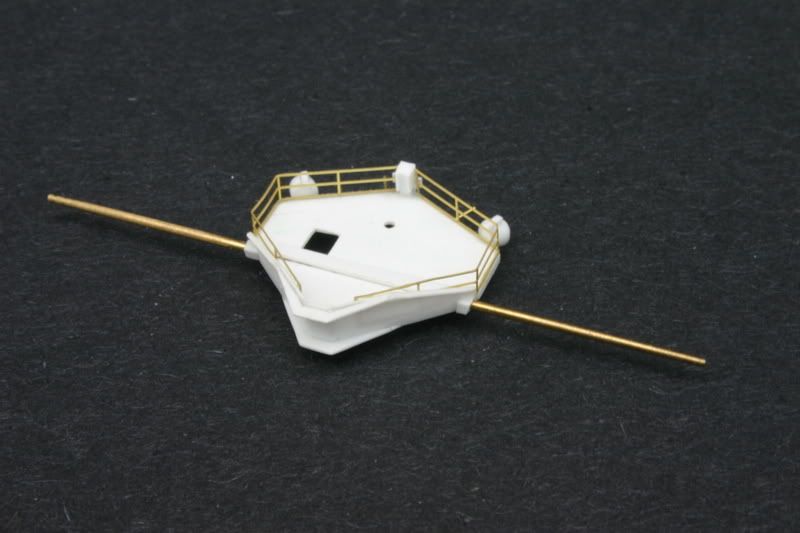
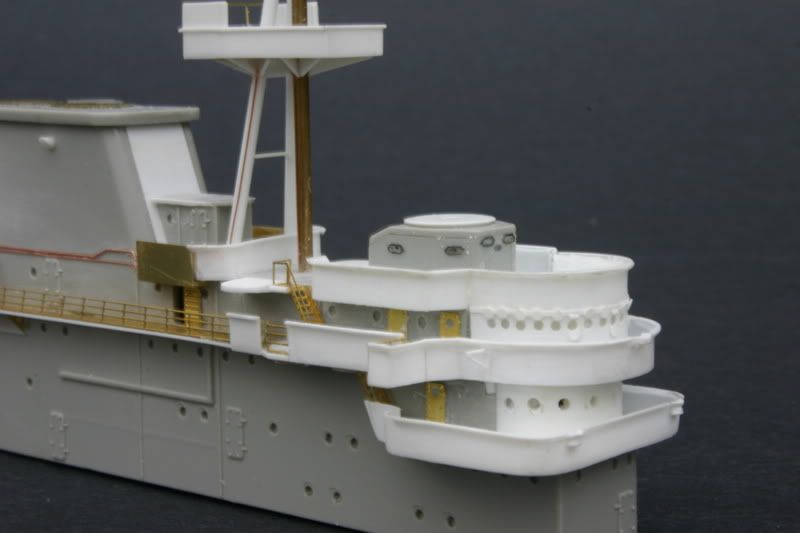
Here are pix of my rebuild of the Trumpy 1/350 HORNET island. The work took longer than anticipated. This was because I had to relearn an old modeling lesson: It is easier to scratch build correct parts than to try to fix flawed ones. I had assembled the basic kit parts some time ago. I intended to go back and correct only the most egregious errors, the symmetrical pilot house and the undersized walkway around it. Referring to the Maryland Silver plan book, the kit island is correct in length but slightly too wide. I chose not to correct this and compensated by adjusting the width of my scratch built parts to match. When I tried to blend my blueprint-based parts to the kit, problems arose. While Trumpeter captured the general look of the island, all of the platforms are just a little bit off in shape and position. I found myself replacing more and more of the kit in order to make things fit. This required working around already completed sections, never a good practice. After several days of struggling, I faced reality, removed all of the platforms, and started all over. The second rebuild went quickly and smoothly (I knew what mistakes not to make) and best of all, everything fit. Some of the alterations made to the ship 1/1942 always puzzled me a bit, but when correctly depicted in 3-D, the rationale behind them becomes apparent.
I�m building the ship in her final configuration as of 10/1942. Here�s the list of what I corrected/added :
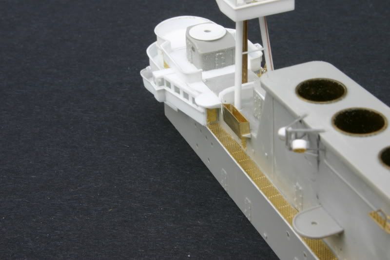
1) The pilot house is completely wrong. It should be wider than the base of the island and offset to the left of the island centerline. The overhanging left side should angle back to where it meets the island�s side. Mike Vorassi has aptly described the correct plan form as being shaped like the loop on a bobby pin.
2) The walkway around it should be correspondingly wider to port, extending straight back, parallel to the island side.
3) The front face of the flag plot (one level below) should mirror the curve of the pilot house. There is no overhang to port. Instead, the curve is bisected by the straight line of the island�s port side, forming a �corner� on the front/left at this level.
4) The walkway around flag plot was originally symmetrical, and should be centered on the island. The port side was altered 1/1942, being cut back at an angle inward aft so as not to impede the view of the flight deck.
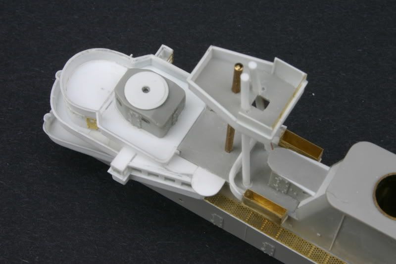
5) Aft of the pilot house, the platform atop the chart house (around the director housing) is too long, too wide, and the front face is incorrectly angled. Immediately aft of it, the platform atop air plot should match in width. Abeam the foremast a semi-circular platform projects on each side, and if the platform over air plot is corrected, these will extend further outboard as they should. Each had a circular platform for a 24� searchlight superimposed, and these should not be centered, but mounted offset outboard.
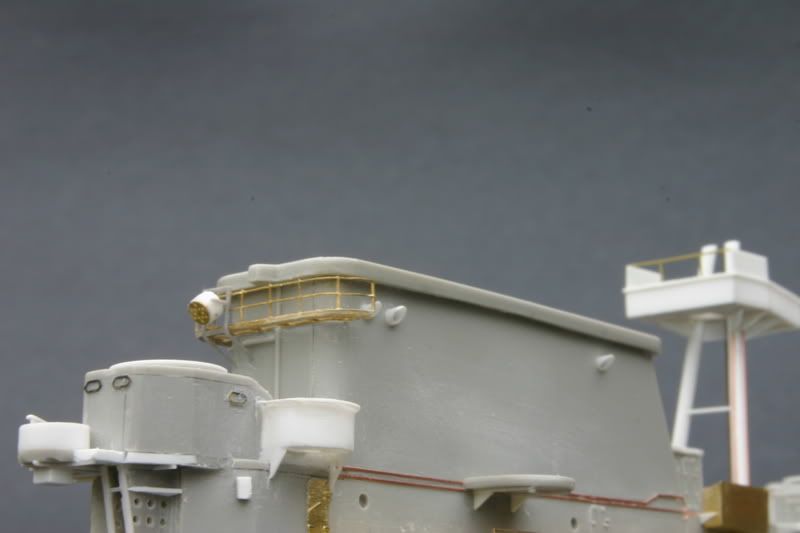
6) Just aft of these there should be a windbreak for the signal bridge. It extends across the island. The outboard ends extend onto small platforms around the after legs of the tripod mast, curving to meet the forward edge of the signal flag stowage bins.
7) The original �L� shaped pri-fly was rebuilt 1/1942. The aft section (parallel to the island) was cutback at an angle in the same manner as the flag walkway to provide better sight lines. The kit part reflects this. However, the forward section is incorrect. The front face should be perpendicular to the island, and not angled as the kit incorrectly depicts. The entire structure is positioned too far forward. It should be relocated with the aft end beneath the semi-circular platform on that side. Scratch building a new pri-fly from plastic stock proved much simpler than trying to correct the flawed geometry of the kit parts. (Correct size and uniform spacing of the windows is the trickiest part, so here�s the �gouge� for 1/350 scale. Front section windows: .060 wide x .080 high, separated by.030. Aft section windows: .100 wide x .080 high, separated by .040.) A triangular shaped ledge runs just beneath the side windows. The windows terminate where the aft section extends beneath the semi-circular platform. There is a door in the aft bulkhead.
8) The kit correctly depicts the 1/1942 alterations to the starboard side of the navigation bridge, but the shielding should be in sections with railing between them. The aft side of the docking bridge should be open, with just railing. . I replaced the walkways with GMM photo-etch parts, which mirror the kit parts. The starboard walkway should extend further aft, and the small semi-circular platform at its aft end is positioned too far forward. The walkway was lengthened and the platform relocated by cutting off the last segment and splicing in a new section.
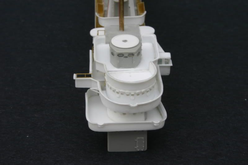
9) The 36� searchlight platforms on the sides of the funnel should be further aft and very slightly higher.
10) Unlike her sisters, HORNET did not have the prominent vertical recess at the front of her funnel. This should be plated in, and the aft end of the signal bridge must be reduced to compensate.
11) The aft island platform is incorrectly angled on the port side and the shielding poorly molded.. There is no walkway on the starboard side and the director housing should fair into the side of the platform. The shielded semi-circular platform on the starboard side is undersized, too far aft and should be elevated higher than the platform.
12) Most of the walkway around the funnel top was deleted 7/1942. A small segment on the aft end was retained to facilitate access to equipment on the mainmast. GMM�s photo-etched parts were modified to reflect this.
13) The foretop platforms were partly cut away 1/1942. The kit parts reflect the alterations. They are reasonably accurate in plan form, but less so in profile (molding limitations). The prominent underside support structure is entirely missing. New platforms and their supports were scratch built.
14) HORNET�s island had large loud speakers mounted in several locations. There was a prominent girder structure on the port side of the funnel near its top for a pair of these. The structure is simply described as a �triangular� mounting, but it is quite substantial and geometrically complex. I could find no 3-D plan, and had to deduce its form and dimensions from the plan view of the funnel top in the MS book and by comparing various photos. If anyone has a more definitive reference please let me know so that I can make corrections.
The rest of the modifications consist of detail improvements. All shielding and windbreaks were replaced with .010 styrene. This was also used to fabricate the support structure for all platforms. The funnel uptakes are brass tube. Photo-etch items are mostly from GMM�s HORNET and HORNET PLUS sets. Some platforms, equipment, and photo-etched fittings have not been attached yet, in order to facilitate painting.
More details to go! The 36� searchlight platforms look clunky, and I plan to replace them with PE perforated ones. I�m not wild about the kit�s searchlights; any recommendations for better detailed replacements? Does anyone have plans of the ship�s siren/whistle mountings or other fittings on the stack top? If you purchased the White Ensign Models HORNET: THE SHIP PE set and did not use the parts for the CXAM radar (it wasn�t installed prior to 7/1942) please contact me. I would like to acquire these, as the GMM CXAM parts are rather 2-dimensional.
Happy modeling!
Mike
>Moved by ArizonaBB39<
-
Devin

- Posts: 2502
- Joined: Mon Jan 10, 2005 10:46 am
- Location: Hoboken, NJ
- Contact:
Mike,
Amazing work. Very clean construction.
When I was working on my Essex island, I was fixing all of the flaws and not having a lot of luck. At that point I didn't know the "just scratchbuild it" mantra. Now that I've been working on my USS Weehawken, I've learned how much fun doing that sort of stuff is with styrene stock. When I return to Essex I'll probably be shaving off some island platforms and shields and just replacing them.
Now, whatcha gonna do about that hull when the time comes?
-Devin
We like our history sanitized and theme-parked and self-congratulatory, not bloody and angry and unflattering. - Jonathan Yardley
-
Charles Landrum
- Posts: 265
- Joined: Sun Feb 19, 2006 6:21 pm
Hornet
Absolutely beautiful work. How did you shape the weather deck bulkeads to achieve the rounded windbreak? I have never seen it done in such a realistic way.
-
Mike Sills
- Posts: 22
- Joined: Wed Apr 18, 2007 8:47 am
- Location: St. Charles, IL
Thanks!
Thank you to all for the kind words. I owe so much to so many for their help through this forum, I just wanted to consolidate the information you have provided and return the favor in some way.
Elvis965 wrote:
Charles Landrum wrote:
Give it a try! Happy modeling,
Mike[/url]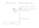
Elvis965 wrote:
The speaker grills are included in the Gold Medal Models PE set for HORNET (350-21). Plastic rod stock was used to form the speakers themselves. .080 diameter was too small, but .100 was too big, so I chucked a length of .100 in a dremel, centered the PE grill on the end with superglue, and turned each piece to match.What did you use to create the loudspeakers? It looks like the side of a PE cable reel?
Charles Landrum wrote:
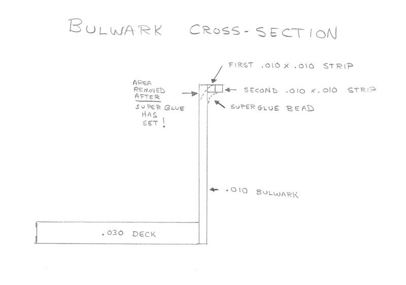
I like working with styrene stock and superglue. The diagram shows my method for building bulwarks. I use .030 for a sturdy deck. The thickness doesn't show, and it provides a firm base to keep the thin .010 bulwarks from warping. The rounddowns are made by attatching strips of .010x.010 with liquid cement to form a lip (you can use .020x.010 on straight sections, but laminating works better around curves). A bead of superglue is then run under the lip and smoothed to form the "front" of the curve. When everything has set, a sharp x-acto blade is used to remove the excess material from the "back" of the curve. A little clean-up with a sanding stick, and Bob's your uncle!How did you shape the weather deck bulkeads to achieve the rounded windbreak?
Give it a try! Happy modeling,
Mike[/url]
-
Elvis965

- Posts: 1059
- Joined: Thu Dec 29, 2005 12:48 pm
- Location: Pittsburgh, PA
Mike,There was a prominent girder structure on the port side of the funnel near its top for a pair of these. The structure is simply described as a �triangular� mounting, but it is quite substantial and geometrically complex. I could find no 3-D plan, and had to deduce its form and dimensions from the plan view of the funnel top in the MS book and by comparing various photos.
Do you have Steve Wiper's Warship Pictorial 9, Yorktown Class Carriers?
There is a close up of the island from port aft on page 51, and I'd say you pretty much nailed it. Triangular structure above & below, rectangular brace in between the 2 speakers, and a brace from the stack to the bottom triangular piece.
Nice job!
Bob
-
Mike Sills
- Posts: 22
- Joined: Wed Apr 18, 2007 8:47 am
- Location: St. Charles, IL
Thanks Mike! You wrote:
I noted that you mentioned this in an earlier post. Can you refer me to a picture of this? Good pictures of the portside of the island seem scarce. Was it off the front of pri-fly?PS, don't forget the stairway down from the roof of prifly down to the navigation bridge walkaround.