The Ship Model Forum

The Ship Modelers Source
It is currently Mon Nov 04, 2024 10:58 pm

All times are UTC - 6 hours [ DST ]


Post new topic Reply to topic  [ 41 posts ]  Go to page Previous  1, 2, 3  Next
Author Message
PostPosted: Mon Jan 14, 2008 9:59 am 
Offline
User avatar

Joined: Mon Aug 14, 2006 3:48 am
Posts: 110
Location: Singapore
Some time passed and here's small update.

Hull is almost finish, only stern left to finish. After making these shoots I have found some places where some touch up is needed (that macro lens...).

Here is overall view of the hull. She's really pretty ship.
Image
Here is the bow with bow bulb. I hope well reproduced. Here for comparison bow shoot of USS Abbot.
Image Image
Here is close up of the hull. Problem I mentioned last time is almost invisible.
Image

Now I'm making extensive source search on hull plating and placement of the all possible hull features (like openings, sonar dome etc.) besides bilge keels, rudder and propellers. I'm going to add all of them.

_________________
God created Arrakis to train the faithful.


Report this post
Top
 Profile  
Reply with quote  
PostPosted: Tue Jan 15, 2008 10:01 pm 
Offline
User avatar

Joined: Mon Apr 24, 2006 4:56 pm
Posts: 934
Location: Berks County, Pennsylvania
Lovely work! :thumbs_up_1: :thumbs_up_1:

_________________
"It is best to remain silent and let others assume you are dumb than to speak up and remove all doubt"

http://nssavannah.wordpress.com/


Report this post
Top
 Profile  
Reply with quote  
PostPosted: Wed Jan 16, 2008 1:31 pm 
Offline
User avatar

Joined: Wed Jan 18, 2006 1:05 pm
Posts: 461
Location: UK
It looks like all the work you put into building the hull certainly paid off - I'm looking forward to seeing more progress. Are you going to start the superstructure + fittings next, or are you planning to add the hull details (bilge keels etc.) first?

_________________
Model Ship Kit Reviews


Report this post
Top
 Profile  
Reply with quote  
PostPosted: Wed Jan 16, 2008 8:33 pm 
Offline
User avatar

Joined: Mon Aug 14, 2006 3:48 am
Posts: 110
Location: Singapore
First I'm going to finish the hull. Main deck still needs some work and small corrections (that's why it is not shown on the photos :smallsmile:). Amount of available data is stunning, so I'm going to add all hull and deck platings, scribbing or adding 0.05 mm styrene sheet where applicable. Fletcher's hull had also some openings for machinery purposes. Only uncertain thing is sonar dome placement and shape. Then I will add standard equipment: bilge keels, propellers with shafts and rudder.
Simultaneously with the main deck I'm going to start also superstructures framing, to ensure that later they will fit the deck curvature as good as possible.

_________________
God created Arrakis to train the faithful.


Report this post
Top
 Profile  
Reply with quote  
PostPosted: Fri Mar 28, 2008 6:09 am 
Offline
User avatar

Joined: Mon Aug 14, 2006 3:48 am
Posts: 110
Location: Singapore
double post -deleted

_________________
God created Arrakis to train the faithful.


Last edited by Sleepwalker on Mon Feb 09, 2009 12:34 am, edited 1 time in total.

Report this post
Top
 Profile  
Reply with quote  
PostPosted: Mon Feb 09, 2009 12:34 am 
Offline
User avatar

Joined: Mon Aug 14, 2006 3:48 am
Posts: 110
Location: Singapore
After looong time I'm back to work on my USS Heermann. It seems that this break was somehow "useful". I have found severe (for me) deformations of the hull skin. :Mad_5: It looks like styrene used for the hull covering was not too good (Tamiya 0.3 mm, semitransparent). Now it creates wavy structure based on the hull sections. Some relaxation process, tension increase ocurred. Anyway I cannot see possibility to fix it using putty - maybe it is possible, but I'm not sure if after some time problem will not come back. For the next projects in styrene I have learned to make filled hull to maintain its shape. I was thinking what I can do now. Start over?... No - too much work was done to end this stage of the work.
New idea is maybe crazy, but why not? I'm going to do... diorama showing USS Heermann during a charge on Japanese cruisers. Luckily hull above waterline due to additional stiffeners is fine. Soon I will show some progress on hull finishing (hull plating etc. above water line and slighty below). I hope to succeed with modified project.

_________________
God created Arrakis to train the faithful.


Report this post
Top
 Profile  
Reply with quote  
PostPosted: Mon Feb 09, 2009 10:39 pm 
Offline
User avatar

Joined: Mon Aug 14, 2006 3:48 am
Posts: 110
Location: Singapore
To show the problem I have made a photo this morning. Sorry for the quality but I had no tripod and daughter was waiting for her kindergarten trip. Hull between frames is retracted with about 1-1.5 mm. After some more carefull watching I have found some other problems assuring me to do waterline model.

Image

On the bottom is attached a strip of the millimeter paper.

_________________
God created Arrakis to train the faithful.


Report this post
Top
 Profile  
Reply with quote  
PostPosted: Tue Feb 10, 2009 5:35 am 
Offline
User avatar

Joined: Sat Jan 22, 2005 10:18 am
Posts: 4131
Location: Liverpool
Hi Sleepwalker sadly this is not an isolated problem when using any styrene based material. For modelers using styrene, the material should come with a warning that it is inherently unstable. But used wisely gives excellent results. The major draw back in its use is the problem of temperature coefficients, especially when used with dissimilar material, timber, metal are just two examples. Styrene responds to changes in temperature particularly when used in large expanses, such as decks or flight deck. Here the problem is magnified were the deck can deform into a severe buckling or wave effect. I tend to be very careful on the extent of the styrene used. I have found that styrene on its own and in an unstressed state is reasonably stable. The problems arise when styrene is married to dissimilar materials,. for practical purposes this may be impossible to avoid. Here I try to limit the amount used to any given area. For me and I can only speak for my self and as a fan of styrene . I would avoid using styrene sheet to form a hull. Modelers on this board have achieved excellent results using this method and could indeed with some justification claim the opposite but it’s long term durability is open to question particularly with working models.
Cheers
Dave Wooley


Report this post
Top
 Profile  
Reply with quote  
PostPosted: Tue Feb 10, 2009 9:58 am 
Offline
User avatar

Joined: Mon Aug 14, 2006 3:48 am
Posts: 110
Location: Singapore
I will try to save my work as much as possible. I almost decided what to do - now point is how do this not destroying everything.

_________________
God created Arrakis to train the faithful.


Report this post
Top
 Profile  
Reply with quote  
PostPosted: Tue Feb 10, 2009 7:30 pm 
Offline
User avatar

Joined: Thu Jul 13, 2006 6:03 pm
Posts: 436
Location: SoCal
it looks realistic... or at least from the pics... any ship that has been at sea for a while has those indentations...

_________________
Reid, PIO of the 48th Fleet
http://www.48thfleet.com


Report this post
Top
 Profile  
Reply with quote  
PostPosted: Wed Feb 11, 2009 3:40 am 
Offline
User avatar

Joined: Mon Aug 14, 2006 3:48 am
Posts: 110
Location: Singapore
Agree, but in the real ship are smaller bumps not over 20 cm like in this case after scale recalculation. Moreover in a real ship frames are much more dense deposited. For Fletcher class it was around 2 feets as I remember - it gives about 3 mm in this scale.

_________________
God created Arrakis to train the faithful.


Report this post
Top
 Profile  
Reply with quote  
PostPosted: Thu Sep 10, 2009 12:20 am 
Offline
User avatar

Joined: Mon Aug 14, 2006 3:48 am
Posts: 110
Location: Singapore
Welcome back after looooooooooooooong break in posting here. But it doesn't mean nothing happened with a model.

I had hard times with my build and I hope that now I shall post here more regularly. My model has changed a lot. But let me describe everything one by one.
First, since at this stage it can be any Fletcher build I decided to rename her to USS Van Valkenburgh. I have found some photos showing her bit unique equipment configuration. Besides like USS Heermann, she has quite interesting history. USS Van Valkenburgh was commissioned as one of the last Fletchers build. She become famous during Okinawa operation where as one of the 10 (!) of the all destroyers used there was not damage. For her actions USS Van Valkenburgh was awarded with Navy Unit Commendation. I like so much also her camouflage Ms 31/9D

Image

I succeeded to remove those "bumps" I shown last time. But price to be paid was high. Extensive sanding caused that all hull shell become very thin and... easy do damage. It happen during one beautiful Sunday, that on almost finished hull felt down Olfa knife (hand side). It opened nice hole. After calming down I checked hull carefully and I have found that it is very thin - like a Japanese paper. Decision was short and executed same day - Dremel tool and cut'em all. So now model is in waterline version.
Well, don't think that cutting of the hull bottom solved everything. Since I applied 1mm styrene sheet to the open bottom I had a lot of problems with cracking hull sides just near the cutting line.
I have found that great stimulator for fighting with all problems was my Wife and her: " I knew that it will happen..." So it did not happened! I was still working on this project. After long weeks of evenings work I have hull ready for further work, ie. adding hull plating and all stuff I will be able to make.

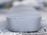
On the photos is a model as yesterday night. Freshly sprayed with Surfacer 1000 (it was planned to be final one, but photos shown some very minor corrections needed to be made. Some more I have found this morning in daylight).
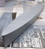

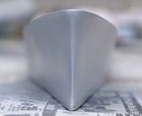
Image Image Image Image

On the hull visible above will be applied 10.mm styrene sheets as hull plating and other things. Of course I need to drill hawse pipes opening too.

Before the disaster I had feeling that something wrong is with the stern (kind of brain itching). Comparing with plans and photos it seemed to be too much rounded. I rescaled part of the BWN plans and compared with the model it was clear that it shall be not so round. I have applied 0.3mm styrene stripes (photos below) and coated everything with a putty. Then a lot of sanding.
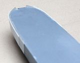
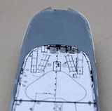
Image Image

Final effect you can see at the photos above. In between the sanding sessions I have prepared internal bracing for superstructures. But there is nothing exciting to show.

That's all for now.

--

_________________
God created Arrakis to train the faithful.


Report this post
Top
 Profile  
Reply with quote  
PostPosted: Thu Sep 10, 2009 1:34 pm 
Offline

Joined: Fri Mar 13, 2009 2:41 pm
Posts: 437
Looks good, you don't give up :thumbs_up_1:

_________________
Someone, somewhere, is making money...


Report this post
Top
 Profile  
Reply with quote  
PostPosted: Thu Sep 10, 2009 10:57 pm 
Offline
User avatar

Joined: Mon Jan 10, 2005 12:47 pm
Posts: 87
Location: Greenville Mi.
I just saw your project. I'll follow with interest. Ive known one of the crew member from her for about 5 years.He's shown me some of his pictures mostly from Korea. He had a bad accident acouple of weekends ago. When he's up to it I'll show him this project. Nice build so far. Great subject.
Rod


Report this post
Top
 Profile  
Reply with quote  
PostPosted: Fri Sep 11, 2009 7:25 am 
Offline
User avatar

Joined: Wed May 23, 2007 10:46 am
Posts: 786
Location: Rio de Janeiro - Brazil
Sleepwalker wrote:
Agree, but in the real ship are smaller bumps not over 20 cm like in this case after scale recalculation. Moreover in a real ship frames are much more dense deposited. For Fletcher class it was around 2 feets as I remember - it gives about 3 mm in this scale.


Rotorhead makes a nice "indentation" here, and very realistic: :thumbs_up_1:

viewtopic.php?f=59&t=40032&start=0

_________________
Make your influence positive!

"Oh Lord thy sea is so great and my boat is so small."
Breton Fisherman's Prayer


Report this post
Top
 Profile  
Reply with quote  
PostPosted: Fri Sep 11, 2009 10:45 am 
Offline
User avatar

Joined: Mon Aug 14, 2006 3:48 am
Posts: 110
Location: Singapore
Thanks for kind words.

Jimmy, please :smallsmile: I just made her mirror like shinning... But after hull plating application... who knows what will happen :cool_2:

Millard, I hope that this former crew member will be fine, and will enjoy my build.

_________________
God created Arrakis to train the faithful.


Report this post
Top
 Profile  
Reply with quote  
PostPosted: Fri Jun 04, 2010 11:31 am 
Offline
User avatar

Joined: Mon Aug 14, 2006 3:48 am
Posts: 110
Location: Singapore
Slowly ahead. Fighting with lack of time, health problems I'd like to show some progress.
First I finished a hull to smooth conditions eliminating all previously mentioned problems.
Then I tried to show deck plating. Basing on BWN plans I drawn all plates - two types: overlaping riveted plates and welded ones. I had some headache with welded plates how to reproduce them in 1/200. Initially I tried fine resin decals from Archer. They looked too big for a scale. Then I decided to scribe them, still getting raised feature. What is shown on the photos is before final fine sanding and is visible under specific light angle. Rivers will be simulated using Archer fine rivets.

Image
Image
Image

With hull sides plating most of the time took me preparing styrene stripes (0.13 mm) with proper shape and dimensions. Anyway I think it looks ok. Looking at the photos I have found some parts to be corrected. Some sanding, and it shall be fine. As shown waterway has been added - 0.5 mm stripe, sanded from the top after gluing to the deck to reduce its height.

Image

Most of the time took me correcting midship superstructure. Initially to the bow side of this supestructure was widened like in case of USS Kidd. Looking again at the plans, and most important hundreds of photos I have found that such feature was used almost exclusively on Fletchers with anti-kamikaze modification (12x40 mm) and some ships modified in mid 1945. It is a little probable that USS Valkenburgh had this area so arranged. Problem with this correction was that... I already glued in superstructure frames as seen on the photo. Some brutal, but still gentle cutting solved the problem, but then a lot of applying putty and sanding to restore the deck. In this area were wegerable lockers ;-)

Image

Next steps will be adding reinforcing riveted stripes on the hull and deck. Then I will apply rivet decals. Later on I will add walls of all superstructures. Than hull painting work and base for a model.

Thanks for now and hope to report soon again.

Damian

_________________
God created Arrakis to train the faithful.


Report this post
Top
 Profile  
Reply with quote  
PostPosted: Sun Nov 07, 2010 11:35 am 
Offline
User avatar

Joined: Mon Aug 14, 2006 3:48 am
Posts: 110
Location: Singapore
Slowly ahead.

I was not too happy with welding imitation I showed last time. I decided to improve them... somehow.

First I sanded them (as well as ripped of superstructure framing - to improve access) off to bare deck then tried to apply stripes of Evergreen profiles (0.5mmx0.25mm). Since they looked to high I sanded them a bit. Effect... Not satisfactory. It was difficult to sand them evenly and besides this 0.5mm looked much too wide for a scale. Sand'em all!
Next I tried Archer resin decals - thin ones, about 0.1mm width. After applying decals I sprayed them with Surfacer 1000, sanded a bit to reduce height and again sprayed. Effect is shown below. These lines are almost invisible, lake in case of real ships. Only certain viewing angles and lightning conditions reveal them. I realize that after deck painting and installing all stuff there it will be almost invisible - but they will be there anyway :-)

Image

As on the photo waterway has been removed too. It was to far from deck edge 2.5mm instead about 1.5mm. I will be there again soon, I hope.

Next step was addition of reinforcement stripes for deck and boards.
Basically Fletchers were all welded, but nearly half of the hull length occupied big, empty spaces of machinery and boiler rooms. It needed some special treatment. Towards bow and stern, welding was enough due to much denser hull structure. Midship was welded with hull and deck platings overlapped and additionally reinforced with riveting. Some plate joints get additional riveted stripes.
Here is how it looks in my case:

Image

Image

Image

Some minor corrections are required and of course all stripes need to be sanded off a bit to keep the scale.

In next step I willl apply riveting. Again from Archer. This will be double rivers, and on the stripes quadruple ones. Well, I deciced to add riveting everywhere where possible. It is a curse of having too accurate sources ;-)

Damian

_________________
God created Arrakis to train the faithful.


Report this post
Top
 Profile  
Reply with quote  
PostPosted: Mon Nov 08, 2010 3:21 pm 
Offline
User avatar

Joined: Sun Mar 07, 2010 12:01 am
Posts: 1665
Location: Corvallis, Oregon, USA
Damian,

The deck weld joints look good. As you say, you don't want them to be too obvious, and achieving this at 1:200 and still having anything visible is no small feat!

Post some photos after you apply the Archer rivets. I will be very intrested in seeing how these work out.

_________________
A collision at sea will ruin your entire day. Aristotle


Report this post
Top
 Profile  
Reply with quote  
PostPosted: Mon Nov 15, 2010 9:43 am 
Offline
User avatar

Joined: Mon Aug 14, 2006 3:48 am
Posts: 110
Location: Singapore
Rivets, everywhere rivets!

As I mentioned Archer just arrived and how it looks like at close, really close distance. Say from 50cm my aged eyes can see continuous line :-)

Image

Appled to the deck. Here without Extra Thin Tamiya coating and without priming.

Image

Some 1m of rivets ahead of me... :-)

_________________
God created Arrakis to train the faithful.


Report this post
Top
 Profile  
Reply with quote  
Display posts from previous:  Sort by  
Post new topic Reply to topic  [ 41 posts ]  Go to page Previous  1, 2, 3  Next

All times are UTC - 6 hours [ DST ]


Who is online

Users browsing this forum: No registered users and 5 guests


You can post new topics in this forum
You can reply to topics in this forum
You cannot edit your posts in this forum
You cannot delete your posts in this forum
You cannot post attachments in this forum

Jump to:  
Powered by phpBB® Forum Software © phpBB Group