NCMac wrote:
MatthewB
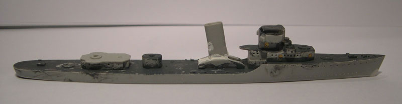
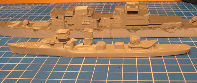
Here was my "quick and dirty" take on the Midship model destroyers for what it's worth.
http://www.shipmodels.info/mws_forum/viewtopic.php?f=60&t=153097Also, some notes I made for another frustrated destroyer builder, again, for what it's worth.
Hull – Typically, the bow curves aft where it meets the waterline like a Japanese destroyer. This should be a straight line and can be easily fixed with a small piece of styrene and some thick superglue as filler. Allow to dry and sand to the correct shape.
If I took a picture of a hull, could you annotate it to show me what you mean?
Quote:
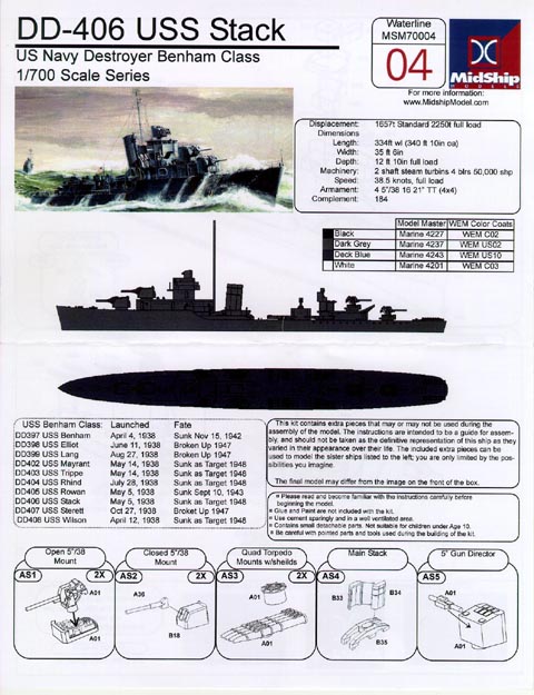
Forward Superstructure – The proportions appear incorrect. The forward 5” mount is too far forward and the superstructure extends too far forward. Remove the gun mount base and the superstructure locating ridges.
Again... I am pretty sure that I understand this one (could probably figure it out), but if I took pictures of the forward deck and superstructure, could you annotate it to illustrate what needs to be done?
Quote:
The aft bulkhead of the superstructure (Parts A27 & A28) should align with the aft bulkhead of the structure on the main deck aft of the forecastle break.
And, here is where I begin to suffer from terminology.
By the "forecastle" do you mean the raised deck of the bow?
And what is a "forecastle break?"
I know what a forecastle is on a Napoleonic Ship (which typically did not have them), And assuming it is the same thing on a Destroyer, then what is the "break?"
Also, I can't identify a bulkhead on one of these.
I know what a Bulkhead is (Structural divider of a ship's hull, dividing the hull into longitudinal compartments with a latitudinal structural "wall").... So... I need a map.
Quote:
There should be a walkway around this as well. Thick card (such as 3 X 5 index cards) or thin plastic sheet works fine. Cut a rectangular piece effectively extending the forecastle deck aft. This also provides a deck to mount the rear portion of the forward deckhouse.
This has to do with the forward superstructure being too far forward?
Quote:
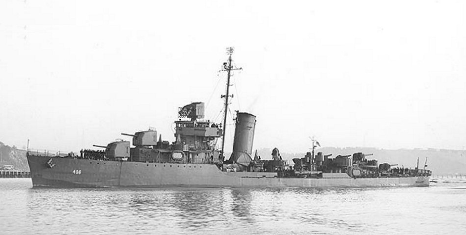
If photo-etched details are used, there will be railings and ladders down to the main deck here. With a good broadside photo or drawing, use a pair of dividers to establish the deckhouse length relative to the forecastle deck length. It varies among the classes but seems to be 50% or less. I definitely shortened the Dunlap deckhouse but can’t remember if I did the same with the Bagleys (very similar to the Gridleys) or if simply getting the aft alignment right worked. Once the forward deckhouse is located, you can locate the #1 5” mount (by eye). The next issue is the pilothouse/bridge structure (Parts A31 & A32) is also too far forward. There is considerable open space between the bridge structure and the #2 5” mount on the actual ship but MidShip has this area very close. Remove the mounting ridges from the deckhouse deck (but wait, as they say, read further). Again, look at your photos and drawings and see where the bridge structure is relative to the forecastle break. MidShip would have it entirely forward of the break but it appears to me to be further aft. I believe the aft bulkhead on each deck level should be directly above one another forming a straight vertical line on the Gridleys. Why wait before removing the mounting ridges? If you replace the deck with thinner stock this is a non-issue. Also notice the 20mm tubs appear too far forward, closer to the #2 5” mount rather than about halfway between the bridge superstructure and the 5’ mount. If you remake the deck (Part A26) you can correct this easily and help with the height issue as well. A new deck (Part A39) for the pilot house isn’t a bad idea either. All the MidShip variants have a solid bulwark aft where it should be pipe railing with flag bags.
Signal flag bags?
Quote:
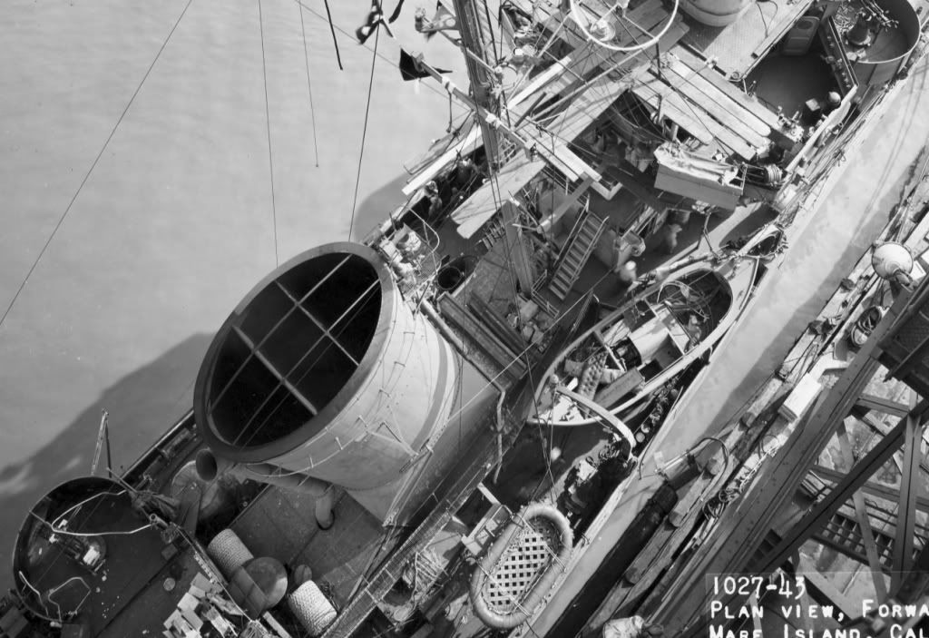
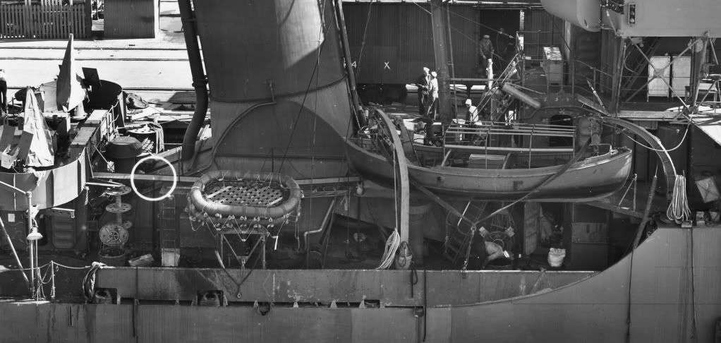
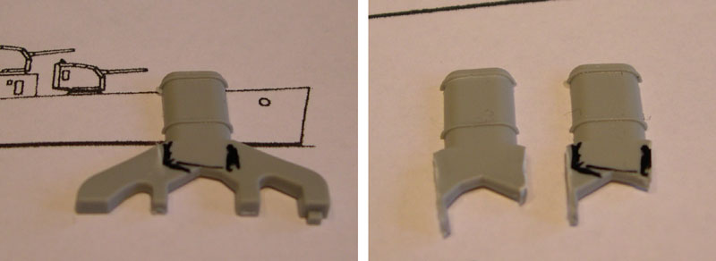
I suspect the biggest issue will be the stack. The MidShip Gridley instructions would have you use the stack for a Bagley which is clearly incorrect. You’ll have to decide how close the options are (I’ve been working on one out of brass tube and styrene for the Benhams for a while now).
OK, now we are somewhere that I know something about (Stacks/funnels).
I know that some of these destroyers had an oval funnel, and some have a flat-sided, rounded-rectangular cross-section. And one seems to have a rounded rectangular, but the sides are slightly pushed in (concave inward).
I can make a stack for any of them in about 20 minutes on CAD to have 3D printed for around $15 (I will need to check the price depending upon material).
But with one printed (or, parts printed for one), then I can get molds made of it pretty easily).
I would just need a reference photo to work from, and some hard dimensions.
If this is an issue, then it is something I would
really like to do, as I am having some issues right now that have made it difficult to do my normal work, and something to make it seem like I am being productive would be welcome.
Quote:
The space for the four torpedo tubes and the aft deckhouse (Part A29 & A30) is very tight. It’s worth laying this out carefully before gluing anything. I think I remember the aft deckhouse as being too far aft making the space between the #4 5” mount and the depth charge racks too close. If you’ve replaced the forward superstructure deck(s), you may replace (Part A15) as well.
I’m not a fan of most of the detail parts provided but that’s just me. You know what you like and I don’t. Use the (detail) parts you’re most comfortable with.
Good luck with your efforts,
Mac
Thanks very much for this rundown. If I get the kit out, then read this with the parts in from of me, then it will probably make more sense.
I have gone through the thread enough to see the walkways (catwalks) around the stacks (can't recall if they were to port or starboard, but that is easy to find out by just going back through the thread).
Also.
I have ungodly amounts of photo-manipulation, CAD, 3D Design, CGI, and Drafting software.
If I can get my head around the description here, I will try to get some photos of the kit to show specifically where these alterations need to be made.
I will just need some help in making sure that I have the right things shown.
MB