Page 2 of 2
Re: HMS Hood: 42 and 45 ft barges
Posted: Fri Feb 20, 2026 9:02 am
by EJFoeth
Intermezzo of the steam launch, preparing for a coat of primer.
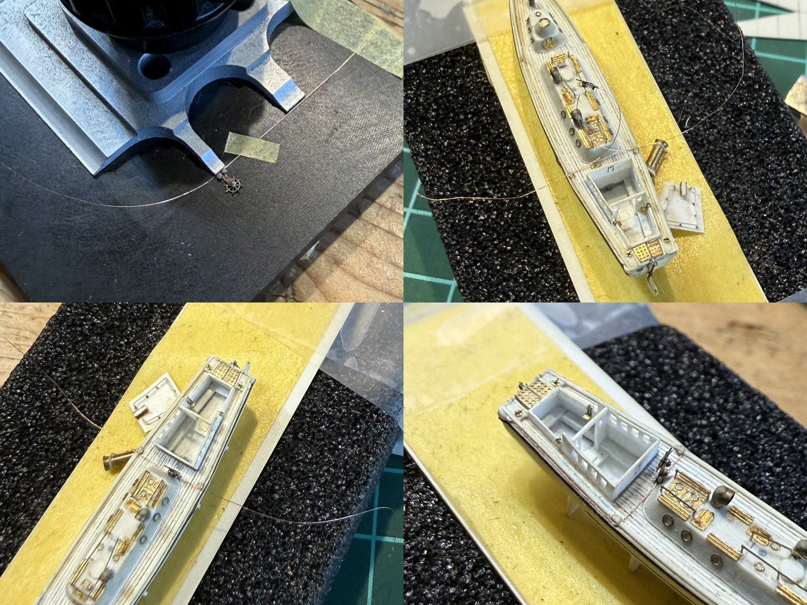
Before painting I had to add a cable connecting the steering wheel to the rudder. I just bought some 0.08 wire added to the steering position carefully removed from the model first. The cable runs on the outside of the hull via a few pulleys, through a small hole of 0.1mm drilled through the spurnwater (?) first. then folded to the back. The cable looks quite clunky in the last close-up shot even though I cannot see that with my optivisor.
Re: HMS Hood: 42 and 45 ft barges
Posted: Fri Feb 20, 2026 11:28 am
by SG1
Mighty!

Re: HMS Hood: 42 and 45 ft barges
Posted: Fri Feb 20, 2026 1:18 pm
by Joelle
Amazing.

Re: HMS Hood: 42 and 45 ft barges
Posted: Sat Mar 21, 2026 10:59 am
by EJFoeth
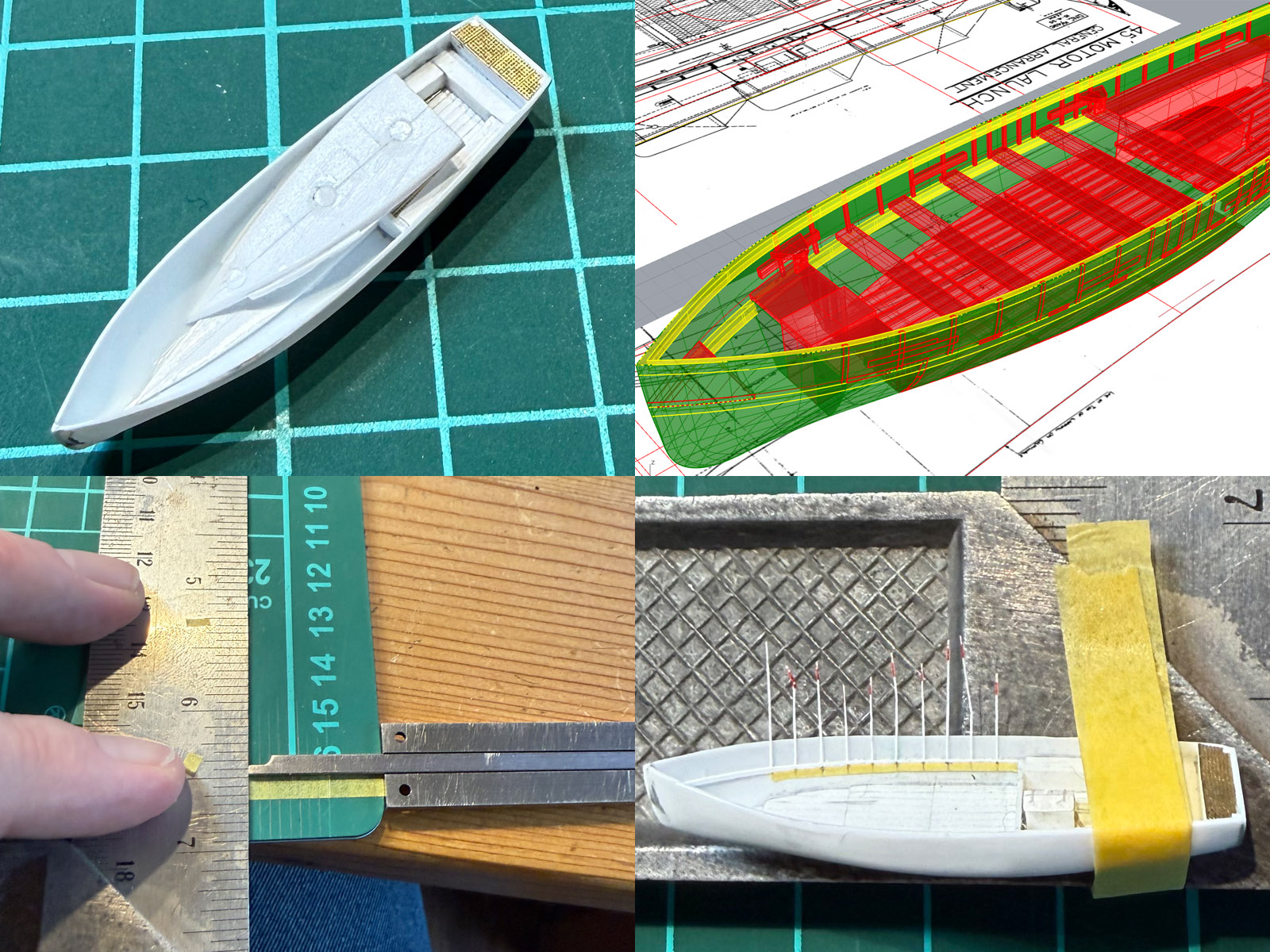
The small transverse bulkhead was fitted and a floor part added; an inset had a few holes drilled in first to see if it would 'touch' the bottom floor part while sanding it to shape during dry fitting. Afterwards these holes were filled and a few strips added to simulate the floor. The outer most planks were added as magic sculpt. The timbers were next, first added to the 3D model (as drawing is fun), then aligned with using marked tape using the depth probe of the calipers to assist.
Bottom strips were all taped into place and cut to size one by one. I needed a small cube in the bow and building it from stacked strip didn't work out so well so I used the milling machine which is just perfect. The space on either side if this cube was filled with magic sculpt and a small floor plate was 'guessed' into the bow. All strips were decapitated to fit the top strake, and photographs show a number of 'timbers' below this strake too; small gaps were added in the timbers to fit these parts. I used a small 'gantry' to help consistent cutting at the right height, sliding this temporary gadget along the top of the hull.
Re: HMS Hood: 42 and 45 ft barges
Posted: Sat Mar 21, 2026 11:23 am
by Edoardo81
I'm impressed by the details you reach in this scale!!

Re: HMS Hood: 42 and 45 ft barges
Posted: Sat Mar 21, 2026 1:35 pm
by MartinJQuinn
Edoardo81 wrote: Sat Mar 21, 2026 11:23 am
I'm impressed by the details you reach in this scale!!
Agreed - utterly incredible work.
Re: HMS Hood: 42 and 45 ft barges
Posted: Mon Mar 23, 2026 5:54 am
by SG1
EJ your scratchbuilding is simply outstanding and a pleasure to see, as always. I admire your precision and the ability to use the milling machine to such a good effect on different materials/occasions. The concept/design/crafting of the gantry was most brilliant
Re: HMS Hood: 42 and 45 ft barges
Posted: Wed Apr 01, 2026 12:05 am
by Dino Carancini
Always a pleasure to watch your works EJ

Re: HMS Hood: 42 and 45 ft barges
Posted: Wed Apr 01, 2026 4:07 am
by wefalck
Somehow, I totally missed the thread until now. OK, the subject is not my area or era ... glad to hear about your successful surgery, another thing I missed ...
Re: HMS Hood: 42 and 45 ft barges
Posted: Wed Apr 01, 2026 7:40 am
by EJFoeth
Thanks all! Also glad surgery went great, was not a trivial procedure and definitely an event you'd want to miss

But I'm fully up & running again and at work including working on these small boats...
Re: HMS Hood: 42 and 45 ft barges
Posted: Tue Apr 07, 2026 4:00 am
by EJFoeth
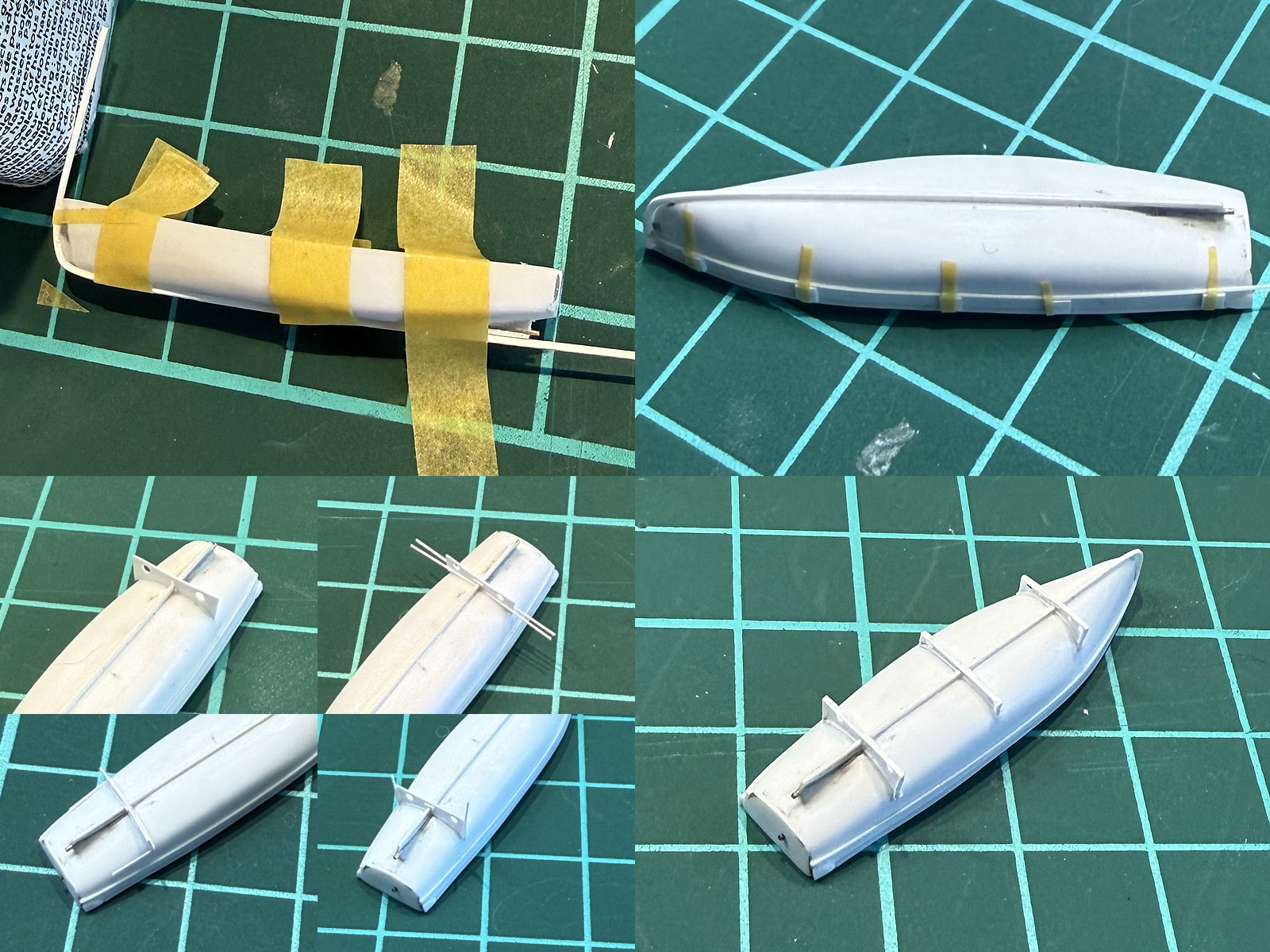
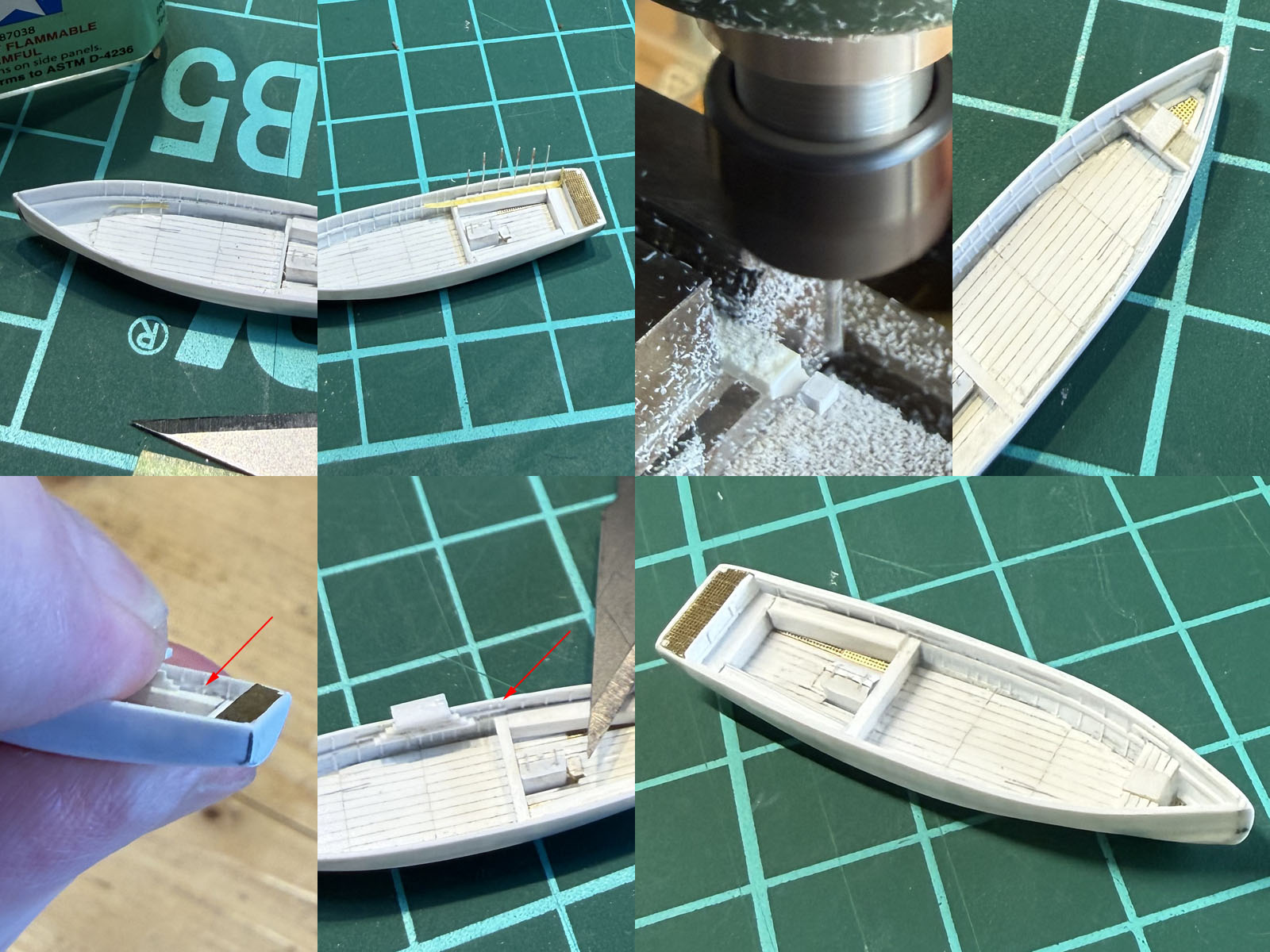
The keel strip was bent in boiling water first; the second rubber was added using a few spacer strips taped to the gunwhale. Crutches were made from strip sanded approximately to size, adding the teak lining using two strips later to hide that the fit between the crutch and the hull is not necessarily perfect (because it never is). Small weight saving holes were added before parting the crutch from the strip by drilling & reaming, hopefully in the right location; otherwise make another one. The crutches for most of the larger boats are positioned right above girders of Hood's boat deck that have a 4ft spacing (12 ft between the crutches), so one would assume each crutch was a tailor-made match between the boat and ship that carried it.
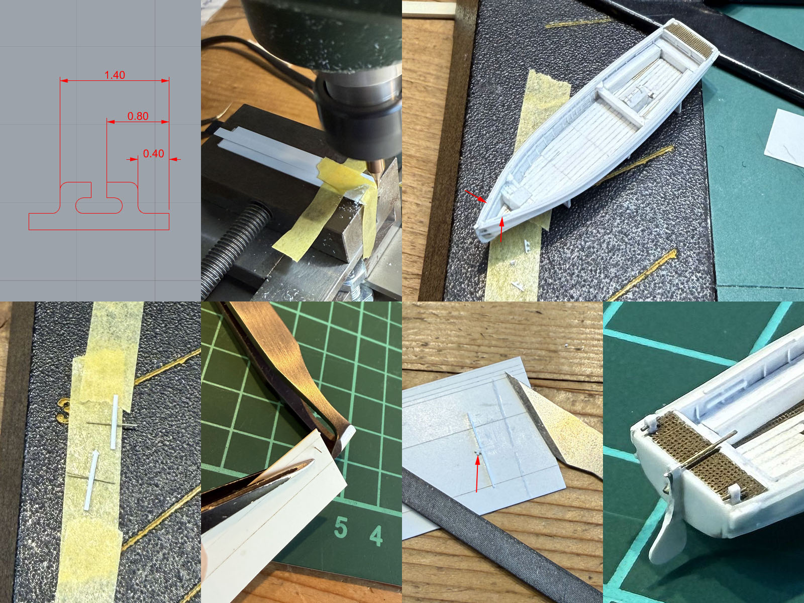
A few tiny tidbits to finalize this model. A cleat was milled using my Proxxon and a 0.2mm milling bit ordered at a Dutch website freesjes.nl. I use a small plastic inset and tape to hold an Evergreen strip down (otherwise the strip would lift during milling) and milling was then very easy to do, though the parts do require cleanup afterwards. Two inserts were scraped into the hull using a 0.3mm Sujibori-do scriber. The first attempt in 0.25mm strip (seen here) was too thin and melted away fully while gluing.... remade them in 0.4mm strip and was glued more sparingly. The characteristic binding posts were next, drilled in 0.4mm strip with a 0.2mm drill (many times before the drilling was done fully straight and up to standards). A 0.2mm rod was inserted, cut to size and sanded using a spacer strip and the strip was decapitated using a small jig made of 0.2mm strip. While all these details are very small they were also surprisingly easy to make and if a part jettisons itself from your tweezers they can be replaced quickly.
Re: HMS Hood: 42 and 45 ft barges
Posted: Tue Apr 07, 2026 10:36 am
by SG1
Great progress, very inspiring. A lot of take-home techniques
Re: HMS Hood: 42 and 45 ft barges
Posted: Wed Apr 08, 2026 6:03 am
by marijn van gils
Fantastic Work EJ!
I learned that I should use tape more often while scratchbuilding. The way you use it for holding the keel in place during gluing, tape guide pieces in place, or even fix pieces on your milling vice, is so simple but makes life much easier. Very clever!
Re: HMS Hood: 42 and 45 ft barges
Posted: Mon Apr 13, 2026 1:55 pm
by JIM BAUMANN
ditto to everything Marijn says-- !

but in addition to tape I also use a lot of Blu-tak for holding things in place
cheers
Jim B
Re: HMS Hood: 42 and 45 ft barges
Posted: Sun Apr 26, 2026 10:56 am
by EJFoeth
Thanks for the comments! And yes, blue tack, know about, read about, seen it used, simply never got around to ordering any
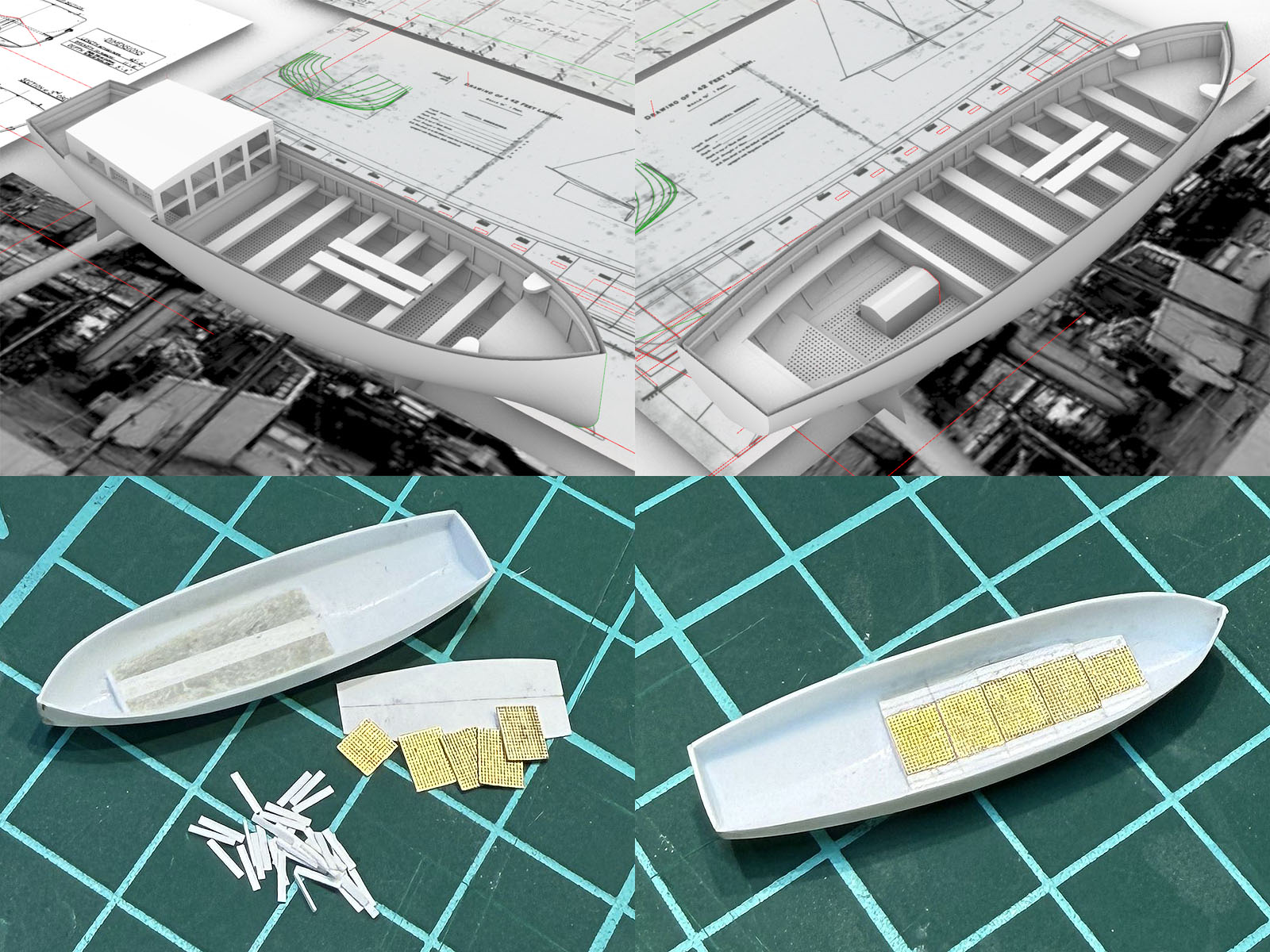
For the next barge I changed tactics. First I did some minor redrawing in Rhino trying to match what precious few photographs I have until
finally accepting there is no more information to be had. The rear seating isn’t very clear, and the main floor I copied from a 36ft pinnace drawing by Underhill, 5 grids of 4 by 5 feet, forward grid narrowed by two planks widths. Now I started from the main floor and will work outwards.
The meshes were cut on a metal surface from the delectable 1:700 WEM Deck Grating once more and glued to a 0.1mm styrene backing plate first with CA; makes it easier to position the parts using normal glue later. A small internal keel was added to the hull with two small end plates; takes forever to shape them to fit the hull. Magic sculpt fills the floor for a solid base. Next a 0.2mm base plate and 4ft by 8in ‘planks’ were prepared using my chopper. After assembly more magic sculpt closed the gaps with plank lines pressed in using knifes and scribers. I’ve only once had one bad experience with magic sculpt with me botching up the mixing ratio, so I always find this part challenging, however this is such a delightful material to work with.
Re: HMS Hood: 42 and 45 ft barges
Posted: Fri May 15, 2026 7:32 am
by EJFoeth
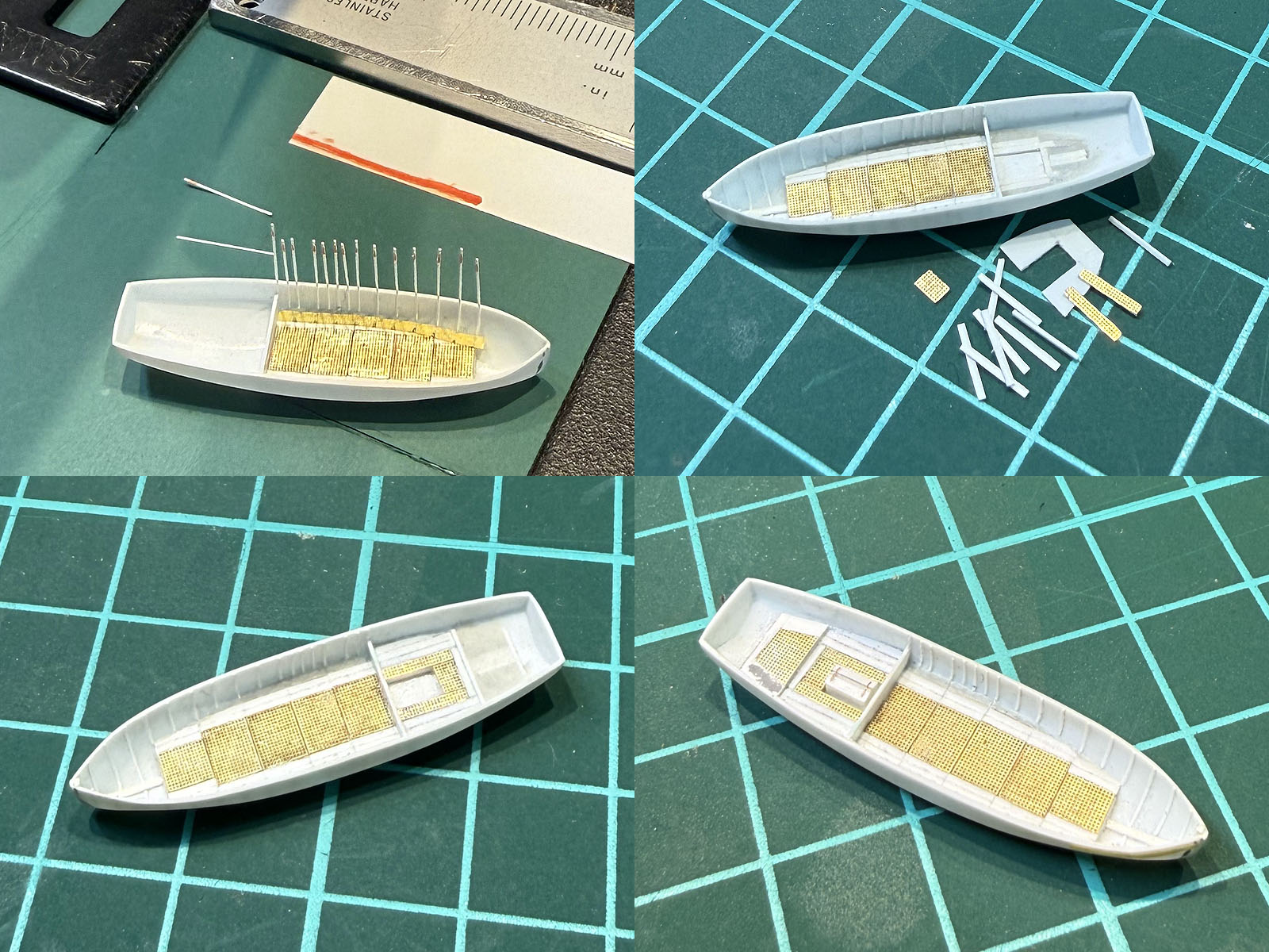
For the aft seating section I though I could make a small insert floor, press into a blob of magic sculpt and all would settle nicely, but that didn't work at all with the insert being too thin and flexible. Attempt one was tossed and the hull cleaned for attempt two. Adding a large keel as a reference as for the forward section is more difficult due to the sloping stern region. So, started with a small strip against the aft of the bulkhead 1.4mm below its top (check with depth probe of the calipers) as a baseline across the section, added a curved keel strip with the right height and at a good angle (check by dryfitting a strip that should be vertical) and topped off with a small plate. Engine location left between some 0.4mm spacer strips, gaps filled off with magic sculpt to form the floor. Strips and more mesh following the same recipe standing by with another bottom plate. The floor for the second section was again made using strips and magic sculpt and finished off with a small floor part; it melted a bit was repaired with putty. The method for the 45ft barge of working downwards from the (solid) seating added first and the floor insert later was easier than working bottom up.
Meanwhile, while the magic sculpt was drying I started with the next boat.
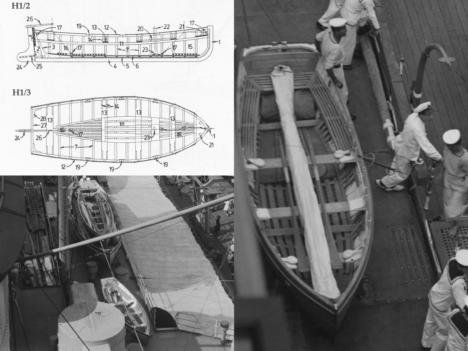
HMS Hood carried two small 16ft dinghy's, according to the AOTS until 1939 when one was replaced by a motorized version---nicknamed the skimming dish---but all three remain visible until late 1941. The sailing dinghy's were stored against either side of the superstructure between the funnels and the skimming dish on the far starboard deck just behind the forward UP launcher. The 16ft dinghy is not as well represented as its smaller 14ft cousin used extensively by the navy for training, see
this page at the BMPT, and of which a drawing by John Lambert was available (L/S/201 while none his work on smaller boats has been reproduced yet I fortunately had a copy). I found a drawing of the 16ft dinghy in the Anatomy of the Ship The Flower Corvette Agassiz,this unsung hero in the series; though no lines were given. Now, the two photographs of the dinghy that I collected, Hood (bottom left) and Nelson, agree well with each other but not so much with the drawing, but it's enough to use these bits of information for new general arrangement. As this is clinker-built the outside might be as time consuming as the inside, but it's only 14 mm long. So how much work could it be.
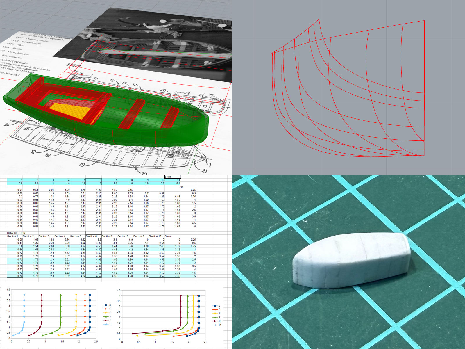
The top view in the first image of the 16ft dinghy shows a slightly different outline compared to the 14ft version, so I simply scaled the lines first to the full beam and then moved the hull lines lengthwise to meet that top view outline (a Lackenby or frame shift). I think the lines of this drawing weren't too well faired; a few waterlines were given but they the bow region was really ill defined. I did some minor refining throwing out the most forward frame and using to top view tangent for all new waterlines and the transom frame was taken from the AOTS drawing. Then an hour or so of “why does Rhino refuse to make a surface” frantic trial and error clicking; this is embarrassing as at work we developed our own hull fairing plugin and we have several CAD engineers specializing in drawing and fairing hulls (far beyond the quality you need for our hobby), I even developed my own spline toolbox to mesh propeller models, but I never got around to acquainting myself with using these tools to get a decent hull. Although it looks ok(ish), the overall quality of the 3D surface is pretty terrible and the inner offset hull has artifacts, but I am not going to print them and it's enough to start the vacuum forming plug. But there still is a lot to learn here if I'm ever going to start building a new large hull. So, the lines in the end look good enough, measurements transferred to open office and a plug made from strips using the default recipe.
Re: HMS Hood: 42 and 45 ft barges
Posted: Fri May 15, 2026 11:48 am
by SG1
Continued over-the-top scratchbuilding and research. It's a pleasure to follow your WIP's, EJ