To Constitution and beyond ...

Moderators: BB62vet, MartinJQuinn, JIM BAUMANN, Jon, Dan K

User avatar
dafi
Posts: 998
Joined: Mon Mar 12, 2012 11:13 am
Location: Ludwigsburg/Germany
Contact:

Re: To Constitution and beyond ...

Post by dafi »

Yupp :-)

Also it can be made longer, by adding another bed to the right side.

XXXDAn
To Victory and beyond ...
viewtopic.php?f=59&t=99050&start=60

See also our german forum for the age of Sail and History:
http://www.segelschiffsmodellbau.com
User avatar
dafi
Posts: 998
Joined: Mon Mar 12, 2012 11:13 am
Location: Ludwigsburg/Germany
Contact:

Re: To Constitution and beyond ...

Post by dafi »

Finally after a long time remounted my rope walk again. For space reasons simply hung in the basement hallway under the ceiling :-)

Image

Then I started rigging to try out the blocks. In the contemporary plans, the blocks are about half the width of the forward wheel. These blocks are minimally larger, which makes handling much easier. To do this, nailed a mounting hook into a piece of wood for holding the hooks. And for that the small blocks do not go off, I always put them immediately on the leash :-)

Image

And here the rigged hook and block from close up.

Image

Image

For comparison in size ...

Image

... and in place.

Image

Since I had pulled down one of the knees with my thick sausage fingers, I immediately took the chance to be able to photograph undisturbed :-)

Image

Image

Image

Image

Image

Image


Greetings, Daniel
To Victory and beyond ...
viewtopic.php?f=59&t=99050&start=60

See also our german forum for the age of Sail and History:
http://www.segelschiffsmodellbau.com
User avatar
dafi
Posts: 998
Joined: Mon Mar 12, 2012 11:13 am
Location: Ludwigsburg/Germany
Contact:

Re: To Constitution and beyond ...

Post by dafi »

Until now, the bottleneck in rigging the guns were the blocks: There were almost no small ones, and if there were, they were often difficult in appearance or quality.

Recently, I have test rigged my smallest self-printed blocks times and noticed that fine thin and steady surgeon hands are needed, including good visual reinforcements.

And I realized that suddenly it is now me beeing the bottleneck ...

Image

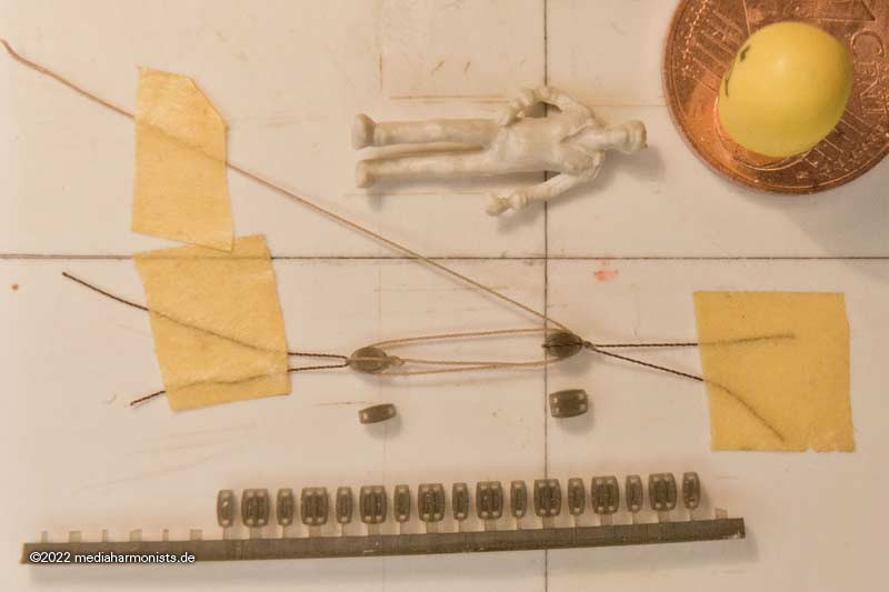
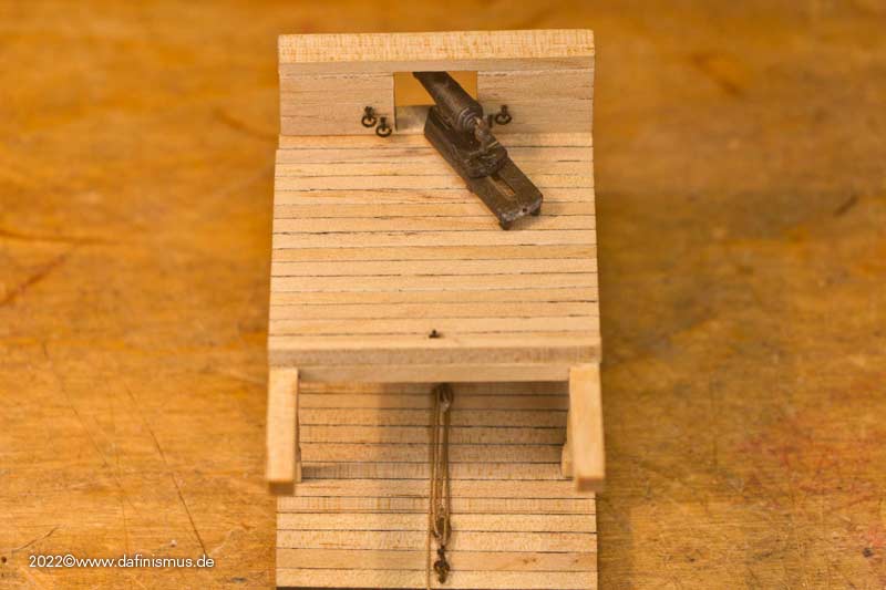
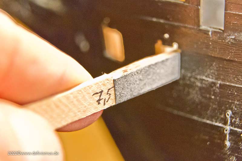
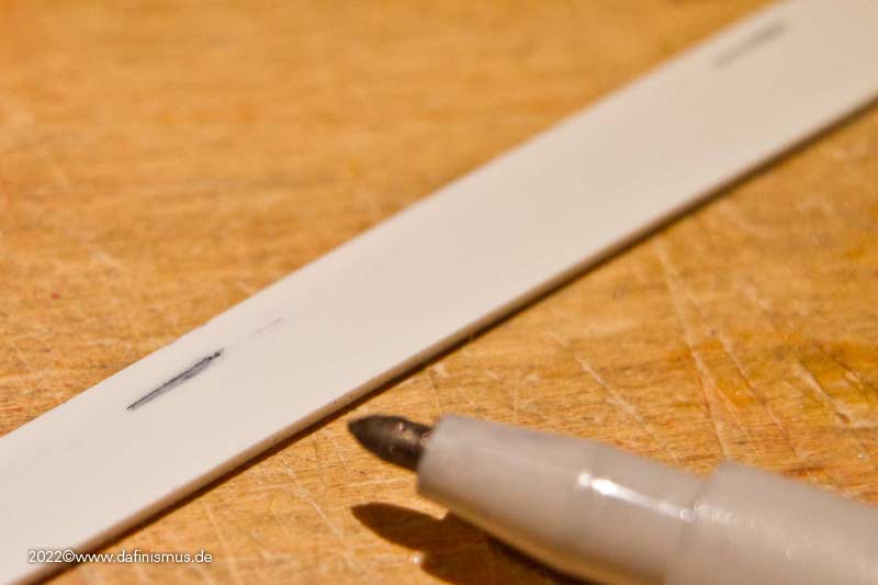
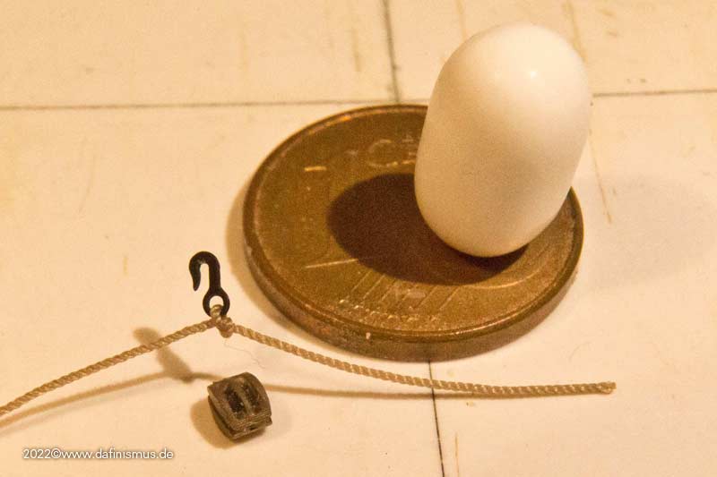
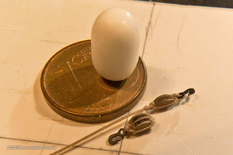
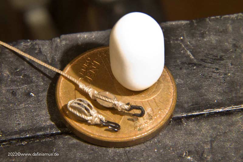
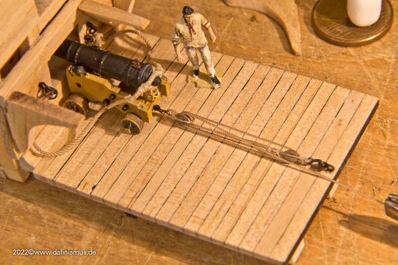
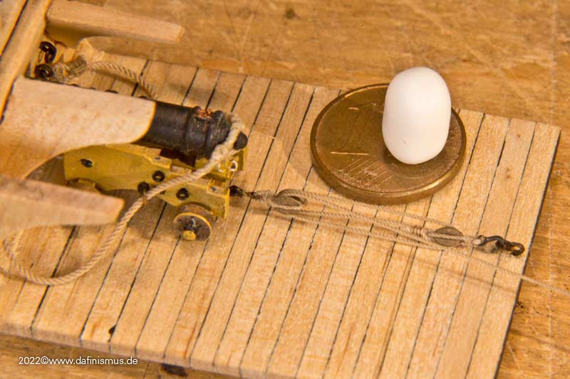
Here the measure of things was the thinnest rope I needed in 1:100, 0.2 mm diameter. Something for the filigran ones among us :-)

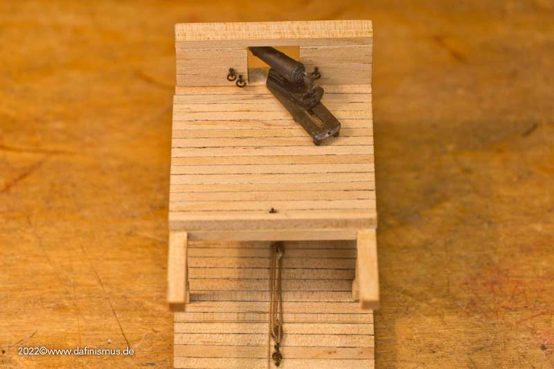
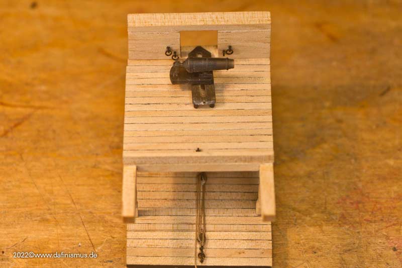
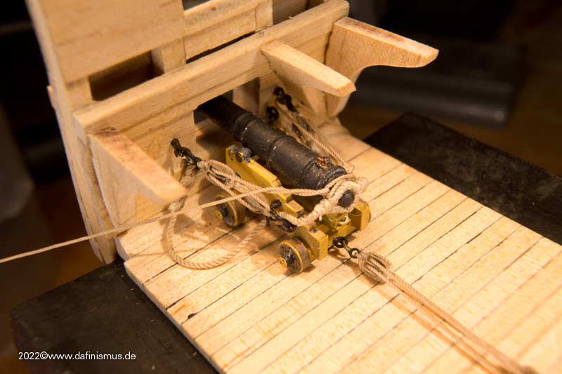
Now the pragmatist in me came out again. According to the old literature I need for the guns in 1:100 / 1:98 the diameter off 0,3- 0,4 mm for the ropes for the lanjards of the side- and back tackles. The 0.4 mm rope is also a common thickness for Gondesen and other suppliers in the aftermarket. So a block combination on this rope thickness is required, and also a good method in which this is done quickly and with good visual results.

It has cost me a few attempts, meanwhile I have found the right variant for myself.

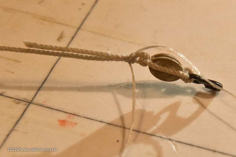
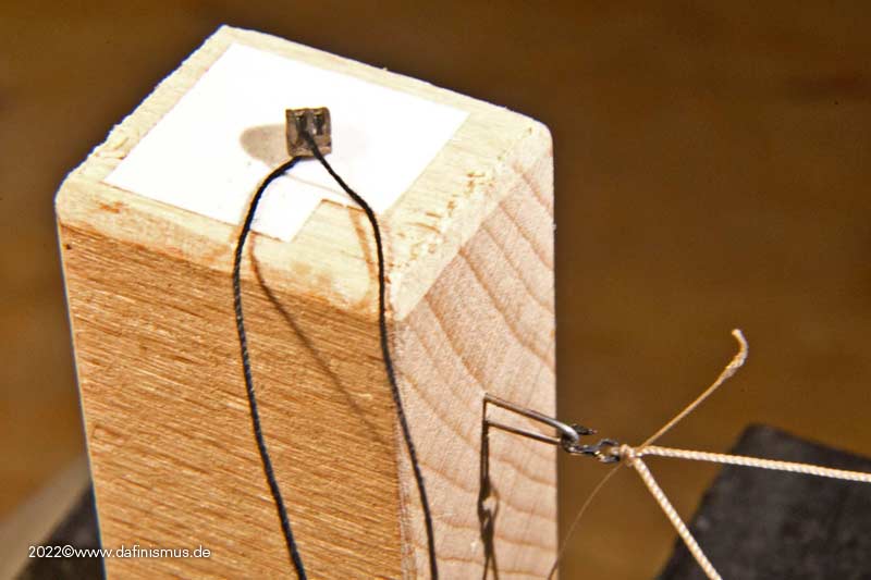
First a normal classical knot to tie the hook in ...

Image

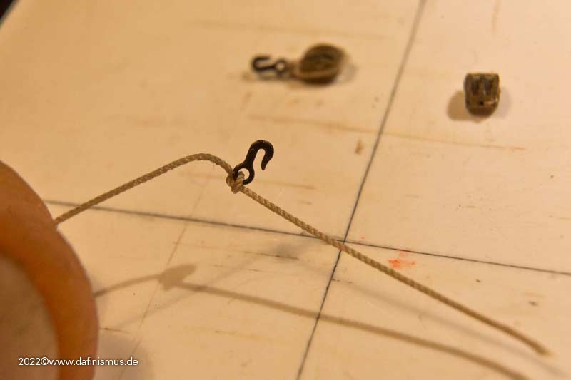
... then the whole thing tightened to the back, in order to make the hook sit well in the middle ...

Image

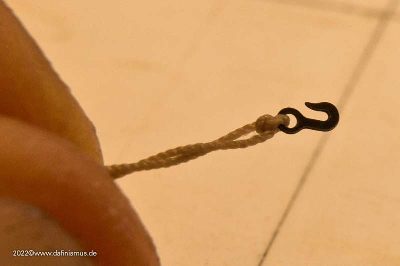
... spreading the ends again and ...

Image

... put the block of choice ready.

Image

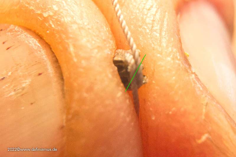
Then clamped the hook between my fingers, used a toothpick to make a drop of super glue in the middle on the knot of the hook and centered the block on it.

Image

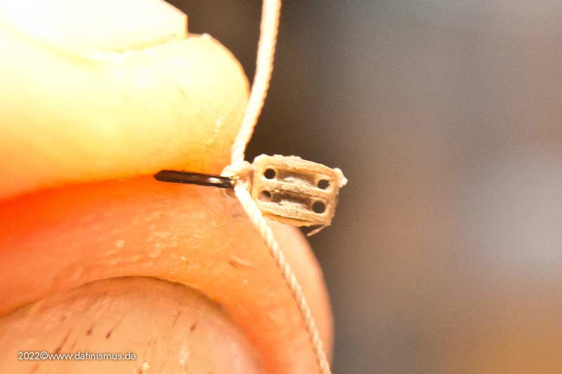
Don't let go of the hook now, but detached it would look like this.

Image

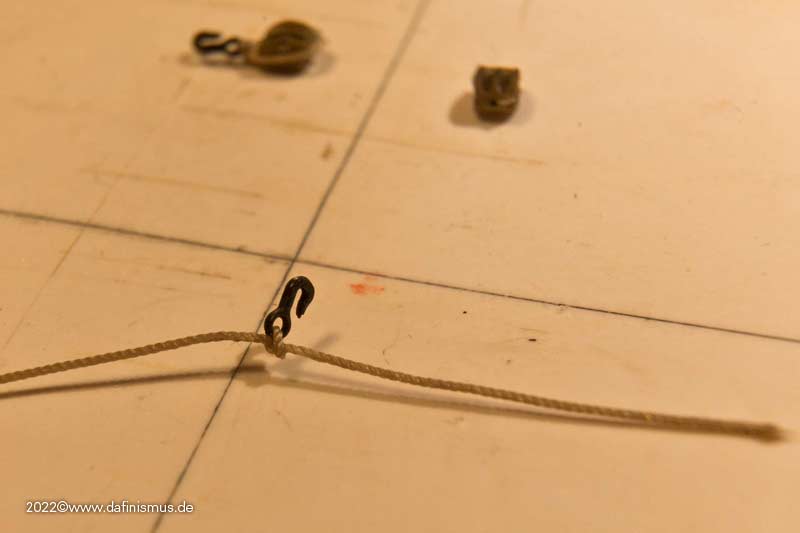
This is just the positioning guide to superglue the groove on the side with the toothpick on one side and pull the rope well over it.

Image

Do not grab the glued area, but pull on the free end. This works quite well without the whole thing forming an inseparable bond with the builder.
Then glue the groove on the other side, pull the rope over it accordingly and make sure that the pull is even and the hook hangs centrally over the block.

Image

Then glue the bottom of the block with the toothpick and pull the ends against each other, cut off the excess diagonally, and press the two slanted ends against each other with tweezers or pliers, securing again with glue if necessary.

Image

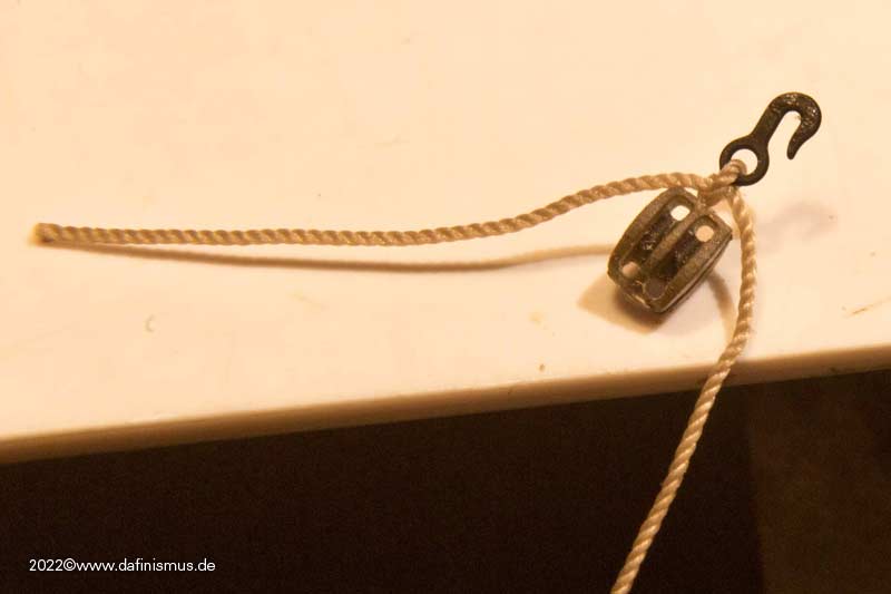
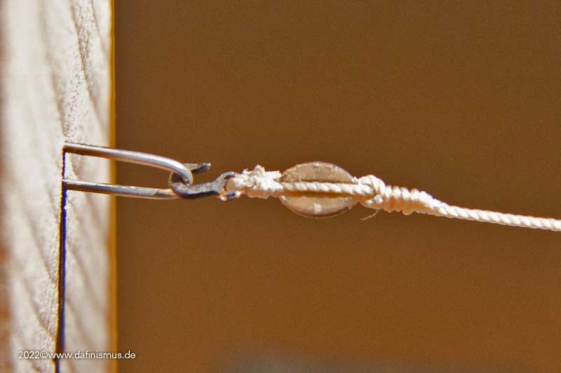
And then you already have it in your hand, the rigged double block :-)

Image

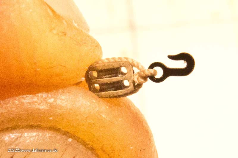
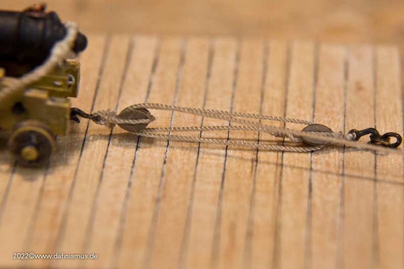
If you want you can strop the bridge between hook block a little bit, but I noticed that it doesn't help that much, so I made it easy for myself here.

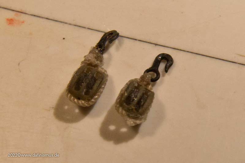
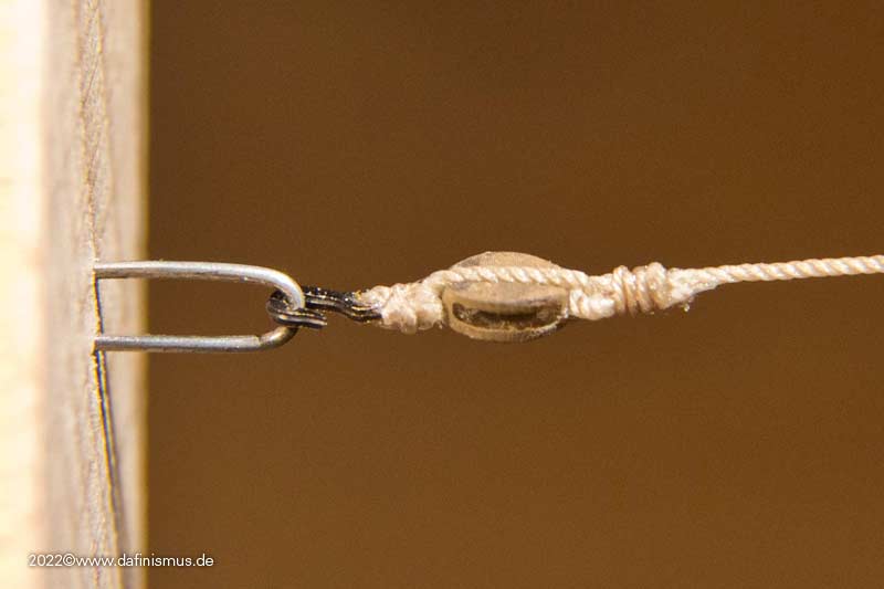
By the way, here is my first attempt, you can still see it somehow crooked, and the one after that, you can see, practice makes perfect ;-)

Image

With the single block it is the same, thread hook on the rope, knot, pull back, spread, hook between the fingers, glue in the middle, block on it to secure, glue the side and pull rope over it, glue the other side and pull over it, and now the difference, on the bottom a knot and secured with glue.

Image

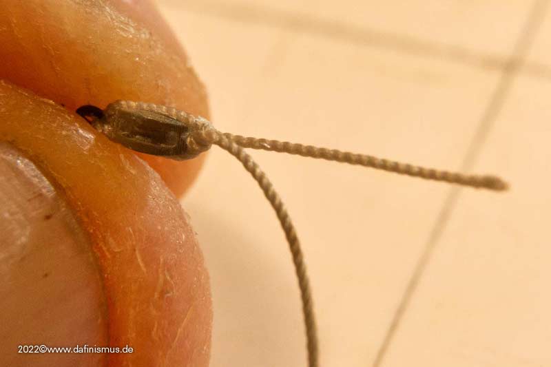
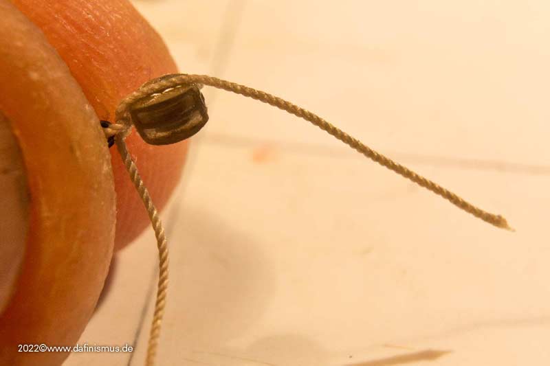
Then the free end stropped up, glued and cut tight ...

Image

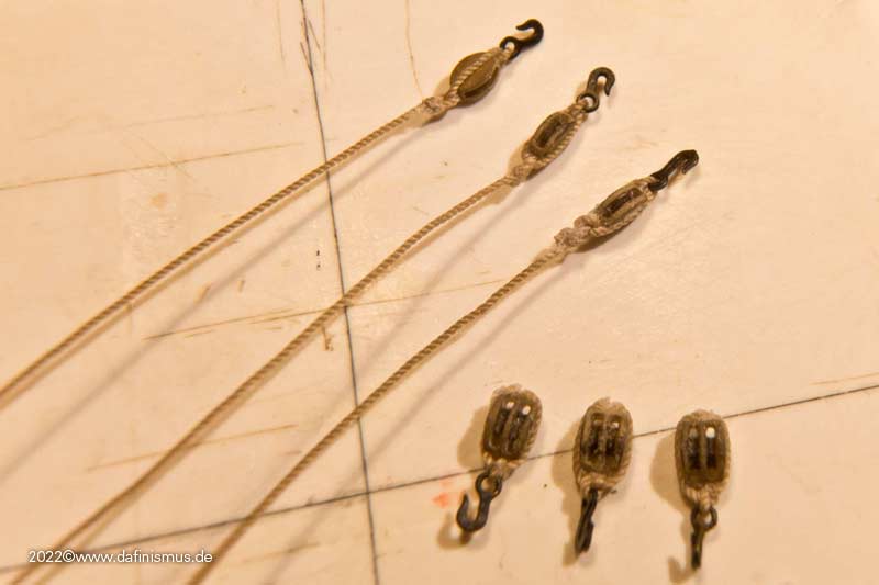
... and the pair of block is ready :-)

Image

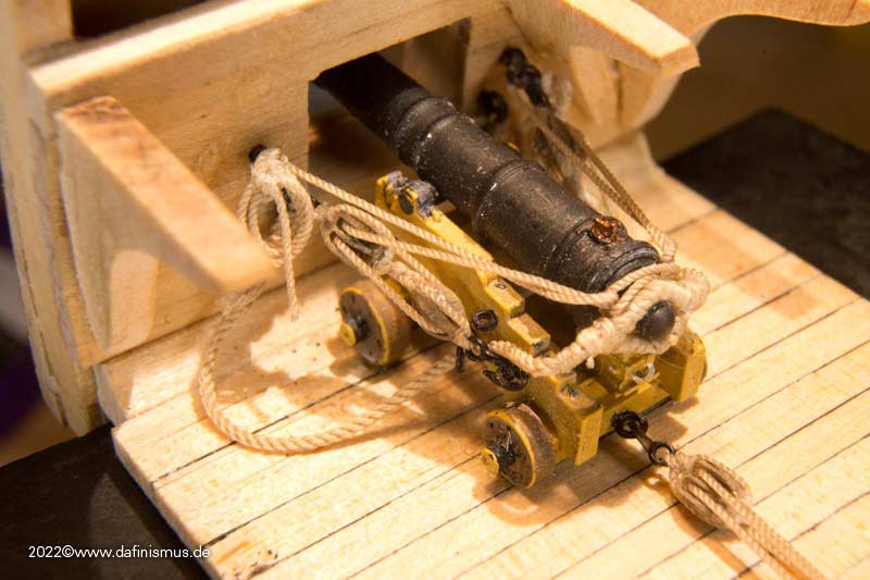
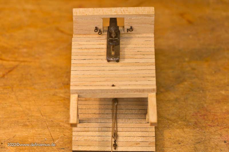
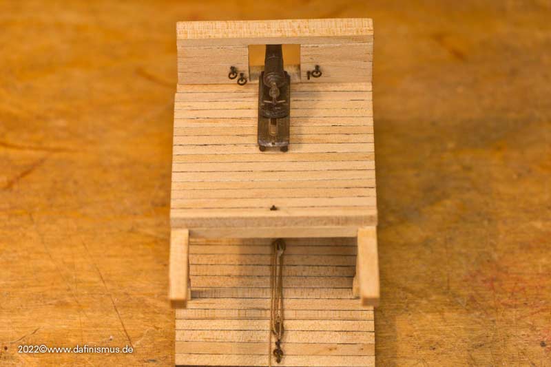
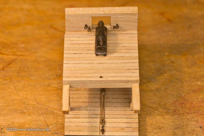
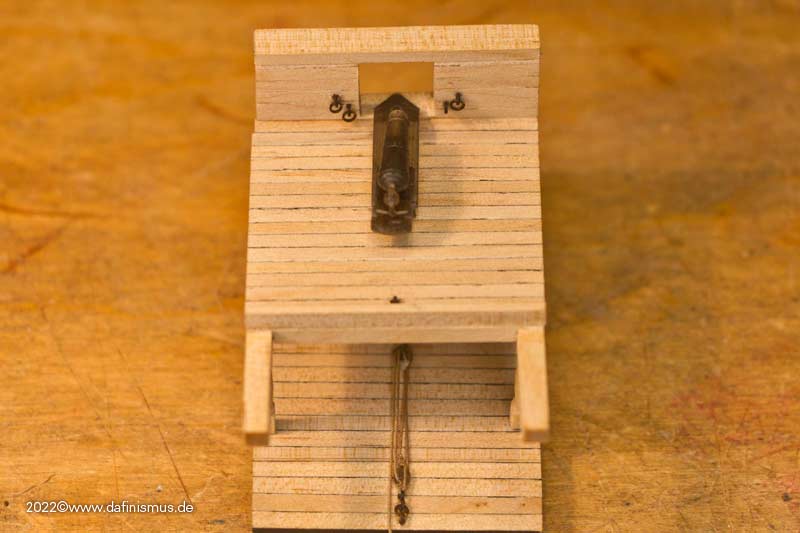
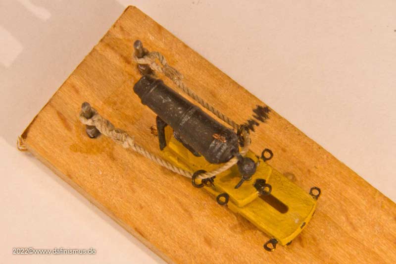
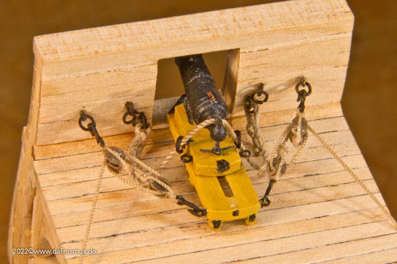
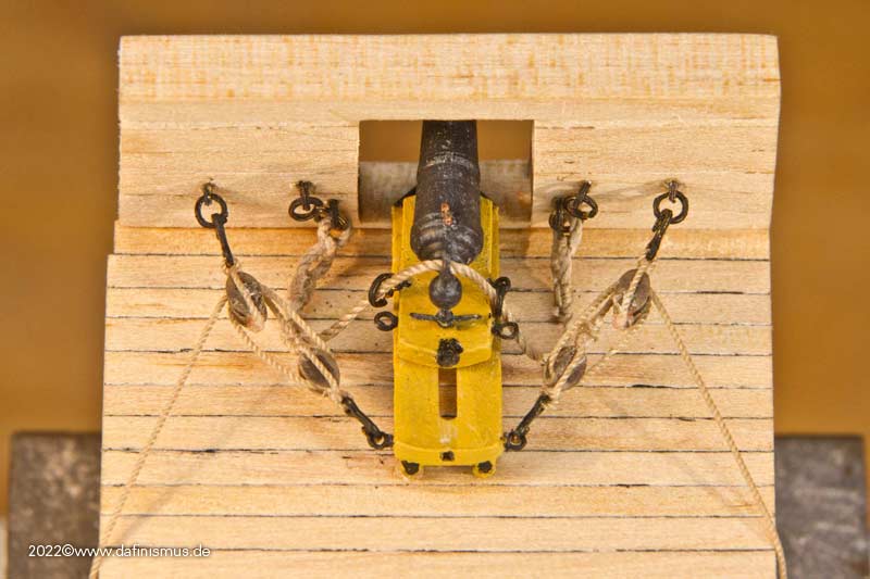
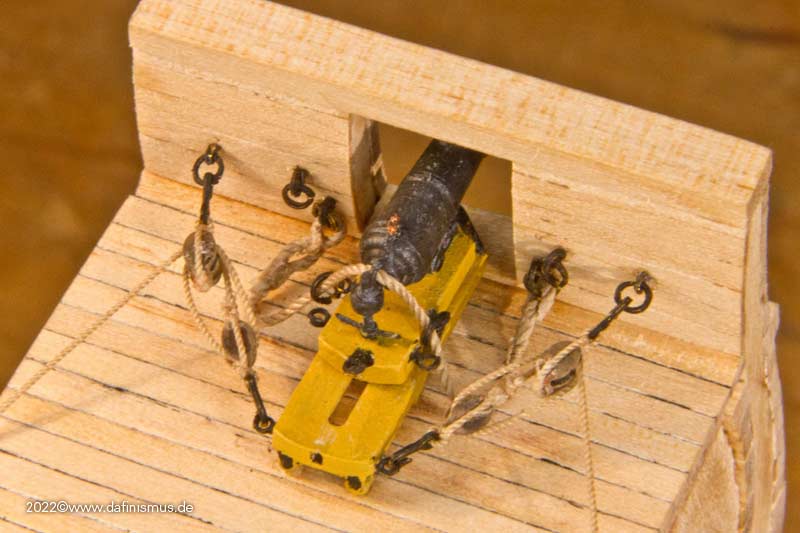
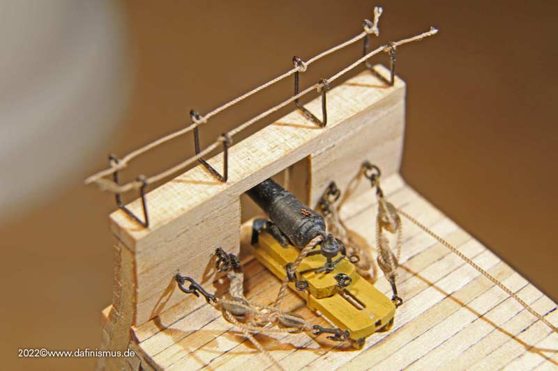
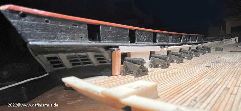
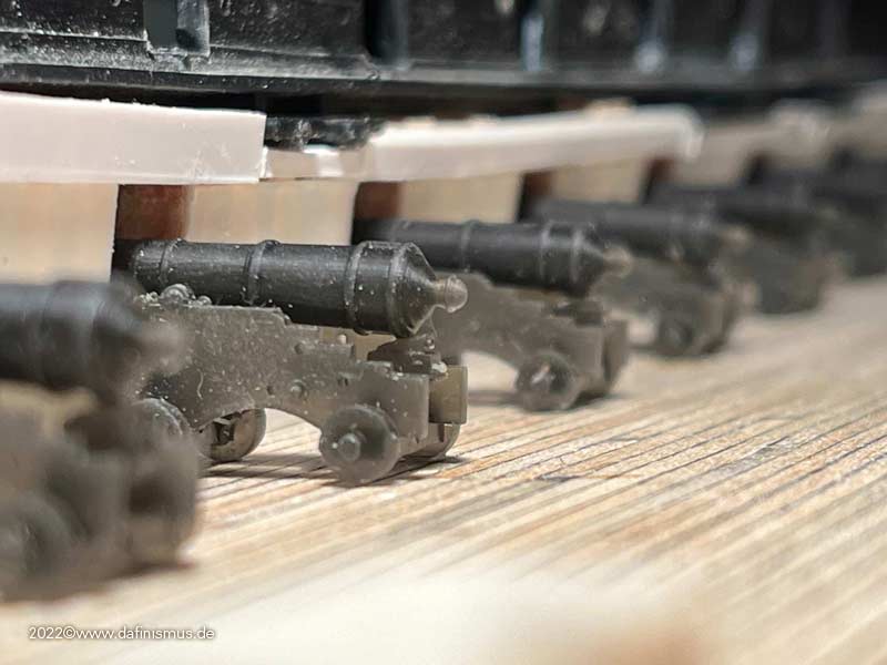
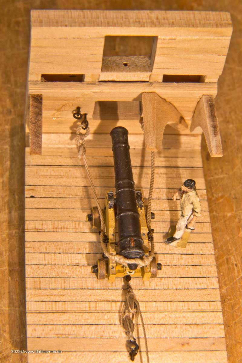
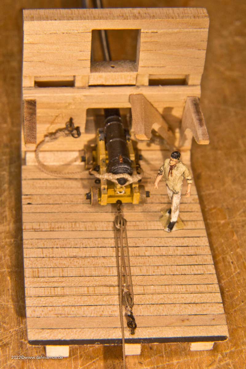
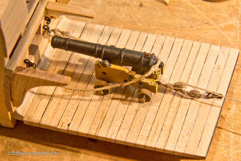
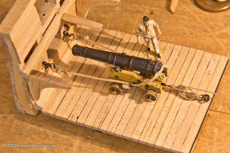
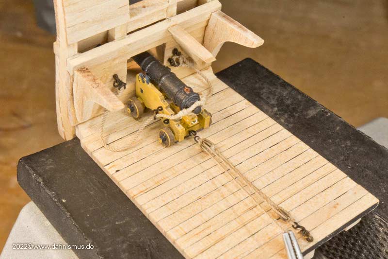
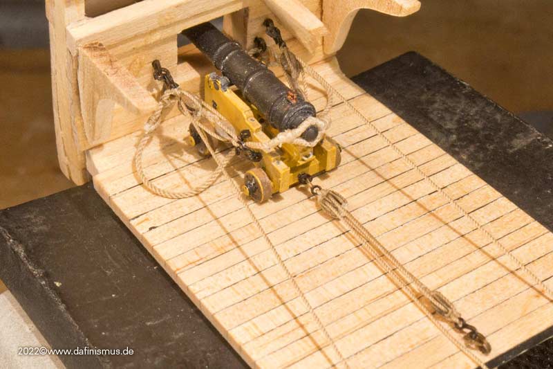
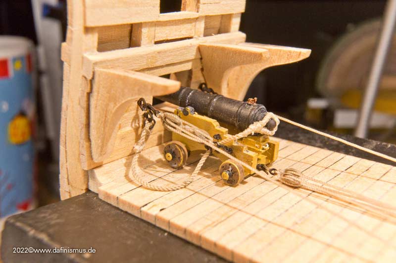
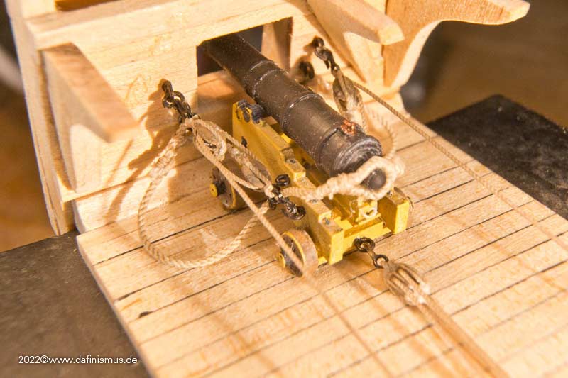
And the other two pairs came together quite quickly, so I soon had a set of three ready for my gun setup.

Image

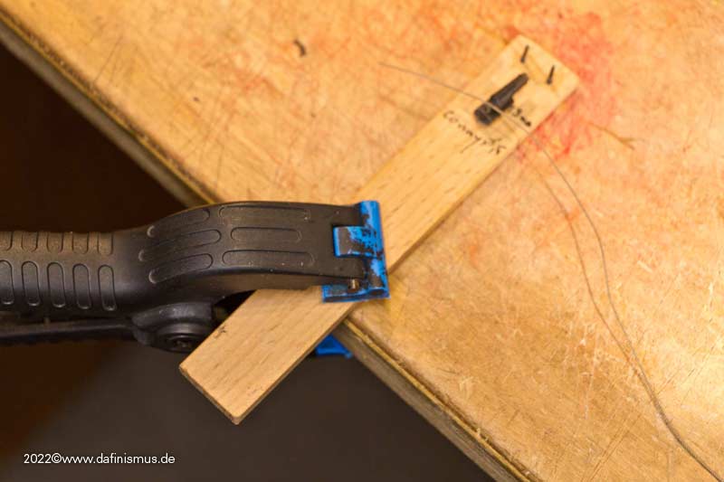
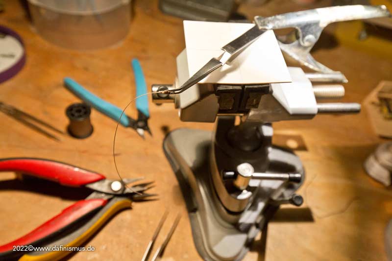
And as I said, no other tools or jigs were needed than a toothpick as a super glue applicator, I only used a pair of self-clamping tweezers on my bench vice to srop on the free end of the single block.

Image

All the best, DAniel
To Victory and beyond ...
viewtopic.php?f=59&t=99050&start=60

See also our german forum for the age of Sail and History:
http://www.segelschiffsmodellbau.com
User avatar
JIM BAUMANN
Posts: 5680
Joined: Mon Jan 10, 2005 5:30 pm
Location: Nr Southampton England

Re: To Constitution and beyond ...

Post by JIM BAUMANN »

Ha! Macro splicing !!

I never cease to be astonished by your drive--and ability
--to pursue the making ( and finding ways of...) of various minutia -!!!

- (seemingly !! ) sometimes...-for its own sake-- because you can ! :big_grin: :big_grin:

in German....-HUT AB !! ==> ( translates as .... Hats off! )

JIM B :wave_1:
....I buy them at three times the speed I build 'em.... will I live long enough to empty my stash...?
http://www.modelshipgallery.com/gallery ... index.html

IPMS UK SIG (special interest group) www.finewaterline.com
User avatar
dafi
Posts: 998
Joined: Mon Mar 12, 2012 11:13 am
Location: Ludwigsburg/Germany
Contact:

Re: To Constitution and beyond ...

Post by dafi »

Thank you Jim!

In between all the X-Mess preparations, I actually managed to get down to business again :-)

Status:

Image

First it was about taking the measurements.

Image

Image

That means at the back the blocks must not overlap ...

Image

... and the front position determines the length of the lanyard

Image

And always the anxious question about the side rigging. After the shot in the retracted position and enough rope for 3 to 5 men to pull, yes there is quite a bit of rope left when the piece is run out again.

Image

Image

Image

But if no one pulls the ropes, it isd mostely displayed directly as running into coils lying on the deck. That has two flaws: First, so the gun can move by itself and slide inward. In addition, the rope is shown mostly in a stretched position that would never be able to run smoothly into the coils, as it obeys gravity that pulls it.

So if no sailor is at hand and secures the free ends, the rope should be secured to the gun, the tackle or the ship's side. On my Vic I had made a half hitch around the aft end of the side tackles, Boudriot shows the "amarage simple" around the cascable. The first attempt went wrong, as at Boudriot there was no splice over the cascable as the breechline goes through the gun carriage, and there it worked well. After some research I found a reference, where the lanyard was led under the eye splice of the breech.

Image

So the free end around the cascable, some turns as required ...

Imageas

... and the rest as a bunch neatly arranged on one of the hooks.

Image

So everything should be neatly tidied up and secured.

XXXDAn
To Victory and beyond ...
viewtopic.php?f=59&t=99050&start=60

See also our german forum for the age of Sail and History:
http://www.segelschiffsmodellbau.com
User avatar
mister me
Posts: 605
Joined: Mon Oct 22, 2012 3:40 am
Location: Vincennes, FRANCE

Re: To Constitution and beyond ...

Post by mister me »

nice rope work !
Damn the torpedoes, full speed ahead! - David Glasgow Farragut
User avatar
dafi
Posts: 998
Joined: Mon Mar 12, 2012 11:13 am
Location: Ludwigsburg/Germany
Contact:

Re: To Constitution and beyond ...

Post by dafi »

And seen from deck�s height it would look like this ...

Image

... scnr ;-)

XXXDAn
To Victory and beyond ...
viewtopic.php?f=59&t=99050&start=60

See also our german forum for the age of Sail and History:
http://www.segelschiffsmodellbau.com
User avatar
mister me
Posts: 605
Joined: Mon Oct 22, 2012 3:40 am
Location: Vincennes, FRANCE

Re: To Constitution and beyond ...

Post by mister me »

fire !
Damn the torpedoes, full speed ahead! - David Glasgow Farragut
User avatar
Martocticvs
Posts: 239
Joined: Tue Jan 26, 2016 7:59 am
Contact:

Re: To Constitution and beyond ...

Post by Martocticvs »

Consitution's hanging knees are positioned under the deck beams then? On British ships, when they were of this design, they were attached to the sides of the beams.

Looking absolultey fantastic!
User avatar
dafi
Posts: 998
Joined: Mon Mar 12, 2012 11:13 am
Location: Ludwigsburg/Germany
Contact:

Re: To Constitution and beyond ...

Post by dafi »

Thank you guys!

@Martocvicvs I had the AOTS as reference, but already realised there are some inaccurancies in there. But that is not the trouble here, as the focus lies on the guns.

In addition to the figurehead of the Victory, I also made some progress with the battle station of the Constitution. First attached the eyebolts for the carronade's gun rig.

Image

Image

To determine the length of the tackles I again documented the different positions.

Image

Image

Image

Image

Image

Image

In the last two pictures, it can be seen that the hooks for the tackles are too close to each other to work effectively because the angle is too tight. That's why two more eyebolts are needed further out.

Image

While this position is technically possible, I think it is a special case that can be well achieved with handspikes if needed.

To tie the breechline, I built a small rigging aid. Hammered in two nails spaced at width of the eyebolts and fixed the carronade in maximum aft position. Then tied the two rope eyes, nice and tight around the nails.

Image

After tying the eye, just pulled them out over the top of the nail, bent the rings up from the eyebolts on the bulwark, removed them, slid them through the eye of the rope, bent them closed again a bit, and reattached them to the bulwark in the eyebolt.

Image

Looks like this then :-)

Image

Image

Image

XXXDAn
To Victory and beyond ...
viewtopic.php?f=59&t=99050&start=60

See also our german forum for the age of Sail and History:
http://www.segelschiffsmodellbau.com
User avatar
JIM BAUMANN
Posts: 5680
Joined: Mon Jan 10, 2005 5:30 pm
Location: Nr Southampton England

Re: To Constitution and beyond ...

Post by JIM BAUMANN »

...sprachlos !!! =..... speechless :wave_1:

JB
....I buy them at three times the speed I build 'em.... will I live long enough to empty my stash...?
http://www.modelshipgallery.com/gallery ... index.html

IPMS UK SIG (special interest group) www.finewaterline.com
User avatar
BB62vet
Posts: 3141
Joined: Mon Nov 18, 2013 3:41 pm
Location: Mocksville, NC

Re: To Constitution and beyond ...

Post by BB62vet »

dafi,

Your carronade look quite similar to the ones I fashioned out of bloodwood for my 1:48 scale U.S. Sloop of War PEACOCK (1813) - these are 32 lb carronades -
Closeup of Main Hatch and Capstan Area (Medium).JPG
Most of the U.S.N. inventory of cannon and carronade carriages were made expressly for a particular ship, so slight variations in the actual shape, etc. The sailing warships are such a wealth of interesting details and so forth for the modeler.

Your work is really well done!!

Hank
HMS III
Mocksville, NC
BB62 vet 68-69

Builder's yard:
USS STODDARD (DD-566) 66-68 1:144, Various Lg Scale FC Directors
Finished:
USS NEW JERSEY (BB-62) 67-69 1:200
USN Sloop/Ship PEACOCK (1813) 1:48
ROYAL CAROLINE (1748) 1:47
AVS (1768) 1:48
User avatar
dafi
Posts: 998
Joined: Mon Mar 12, 2012 11:13 am
Location: Ludwigsburg/Germany
Contact:

Re: To Constitution and beyond ...

Post by dafi »

Thank ypu Jim and Hank, very appreciated!

Then attached the hammock cranes with the netting.

Image

Mounted the white net in the cardboard frame and first primed it with white and then colored it slightly brown.

Image

Then inserted two strips of paper as a convenient insertion aid and inserted the net with a wooden core.

Image

Then on the outside, fixed the net with super glue at points, widened the core so that the net fits well on the inside of the holders, and also fixed the back side of the net at points. Then removed the core, glued the net well to the top rope and trimmed everything well with the pointed scissors.

Image

After that, some more trimming was done and next comes the hammocks.

Image

Image

XXXDAn
To Victory and beyond ...
viewtopic.php?f=59&t=99050&start=60

See also our german forum for the age of Sail and History:
http://www.segelschiffsmodellbau.com
User avatar
dafi
Posts: 998
Joined: Mon Mar 12, 2012 11:13 am
Location: Ludwigsburg/Germany
Contact:

Re: To Constitution and beyond ...

Post by dafi »

The dimensions of the hammocks are well known. The diameter of the rolled sausage also can be seen in contemporary drawings. Even if they were sometimes thicker, because blankets were still rolled in, I choose the thinner version without additional content. Contemporary sources show 7 to 9 laces. Some say like the 7 oceans, on Bray's sketches you can see the variant with 9.

The mats were rolled of Fimo, the laces rolled in by means of a special comb. Since the holders are very low, I first tried the straight variant.

Image

I found the bent variant better, as it is also historically documented in many cases.

Image

After that, a bit of 50 shades of beige , plus some ink for shadows and depth and the lacing in the visible area represented with thin yarn and it all fits so far for me.

Image

Image

Image

XXXDAn
To Victory and beyond ...
viewtopic.php?f=59&t=99050&start=60

See also our german forum for the age of Sail and History:
http://www.segelschiffsmodellbau.com
User avatar
dafi
Posts: 998
Joined: Mon Mar 12, 2012 11:13 am
Location: Ludwigsburg/Germany
Contact:

Re: To Constitution and beyond ...

Post by dafi »

I'll come back to the Battle Station later to still add some life. But it was time to do some stretching.

First off, built a sturdy stand.

Image

Then came bondage. The hull is unfortunately so warped, that here rougher force in the form of tight lacing had been necessary.

Image

The lacing allowed me to spread the load better. Still, later the hull partially burst open again, so the rougher tools came into play. Result was that it finally lasted ...

Image

... but as collateral damage the hull had become quite wavy. Later on, the insertion of the upper deck will be a even-ing challenge ;-) (Mark the bun!)

Image


The next step was to double up the ship's side. This makes the difference between the appearance as a classic plastic kit and upscale modeling appearance. Built up a small stop to do the doubling.

Image

Then glued inside 4 mm battens against the stop.

Image

Image

Then inserted the sills at the top and bottom, making sure that there is enough overhang in each case. The space between these port frames was also filled with battens.

Image

If there is too much protrusion of the sills, this is first minimized them with a sharp tool.

Image

Then cut a flat batten to sand down the remaining overhang at the top/bottom, with minimal undersize in the sanding area and slightly more on the opposite side port. Taped 240 grit sandpaper to it with double sided tape, that fits well with my rather soft battens.

Image

The strip is passed through the port on the opposite side, this gives an even horizontal angle.

Image

Then sanded the sill on top ...

Image

... turned the batten over and sanded the bottom sill.

Image

Prepared another sanding strip for the sides ...

Image

... especially in the bow area at the idle ports, some rework is needed because of the strong bend.

Image

And this you get as comparison: original version Revell ...

Image

... and the revised version :-)

Image

XXXDAn
To Victory and beyond ...
viewtopic.php?f=59&t=99050&start=60

See also our german forum for the age of Sail and History:
http://www.segelschiffsmodellbau.com
User avatar
JIM BAUMANN
Posts: 5680
Joined: Mon Jan 10, 2005 5:30 pm
Location: Nr Southampton England

Re: To Constitution and beyond ...

Post by JIM BAUMANN »

Ha!

The strip is passed through the port on the opposite side, this gives an even horizontal angle.

now THAT is really a most useful hint !! :thumbs_up_1:
question;

I assume the deck camber is so slight there is no danger of accidental sanding of the planking..?

MFG ( KR ) Jim Baumann :wave_1:
....I buy them at three times the speed I build 'em.... will I live long enough to empty my stash...?
http://www.modelshipgallery.com/gallery ... index.html

IPMS UK SIG (special interest group) www.finewaterline.com
User avatar
dafi
Posts: 998
Joined: Mon Mar 12, 2012 11:13 am
Location: Ludwigsburg/Germany
Contact:

Re: To Constitution and beyond ...

Post by dafi »

Thank you Jim, no no danger at all. Even the correct camber would leave plenty of space, but to tell the truth, the kit has no camber at all ...

XXXDAn
To Victory and beyond ...
viewtopic.php?f=59&t=99050&start=60

See also our german forum for the age of Sail and History:
http://www.segelschiffsmodellbau.com
User avatar
dafi
Posts: 998
Joined: Mon Mar 12, 2012 11:13 am
Location: Ludwigsburg/Germany
Contact:

Re: To Constitution and beyond ...

Post by dafi »

After all the battens were mounted, the cleaning up really started. Rough overhang was minimized with the scalpel, then the top and bottom were filed with the sandpaper battens as already described.

Image

I also made a small tool for the inner surfaces.

Image

For the bow area there was something more shorter and rounded.

Image

After everything was smooth enough we went to the spirketing. A 1 mm thick polysterol strip at the bottom, 0.5 mm Polsterol between the ports, and another 1 mm above that.

Image

Image

And the fit sample.

Image

Fits :-)

To fit the lower strip, press it well inside ...

Image

... on the outside, score the lower edge of the port with a scalpel ...

Image

... make the scribe visible with paint, i.e. color it and wipe away the paint on the outside so that only the depth of the scribe remains colored ...

Image

... and cut off the overhang based on these marks and glue this adap�ted stripe in. Between the ports, orient the 0.5mm strip to the height of the ports. If you have worked evenly when filing the ports should be always the same height.

Image

And the one side is ready.

Image

Image

Image

Now the other side and then the head area and the side galleries areas.

XXXDAn
To Victory and beyond ...
viewtopic.php?f=59&t=99050&start=60

See also our german forum for the age of Sail and History:
http://www.segelschiffsmodellbau.com
marijn van gils
Posts: 2686
Joined: Tue Feb 06, 2007 10:24 am
Location: Belgium

Re: To Constitution and beyond ...

Post by marijn van gils »

Wonderful work! This makes a big difference to the overall feel indeed :thumbs_up_1: :thumbs_up_1: :thumbs_up_1:
User avatar
dafi
Posts: 998
Joined: Mon Mar 12, 2012 11:13 am
Location: Ludwigsburg/Germany
Contact:

Re: To Constitution and beyond ...

Post by dafi »

Thank you Marijn!

In order to get a little more structure into the few possible views into the lower deck, I have printed the characteristic triple knees of today's Constitution. Whether these were already in place in earlier eras of the ship or if they were only installed during later conversions is beyond my knowledge. I would have instinctively guessed the classic use of 3 separate knees for the early phase of the ship. I would be happy to take any hints on this.

Image

Due to the kit, I can't work with deck beams because the ship has to be pressed into shape by the upper deck. Therefore, I have to skip the upper part of the knees too.

Image

Image

Image

Image

Placement check with guns.

Image

And in the end it's all about such a view anyway :-)

Image

XXXDAn
To Victory and beyond ...
viewtopic.php?f=59&t=99050&start=60

See also our german forum for the age of Sail and History:
http://www.segelschiffsmodellbau.com
Post Reply

Return to “Works in Progress”