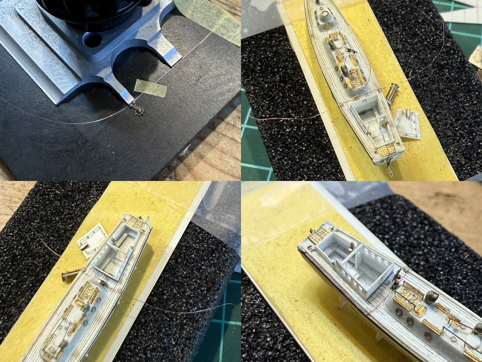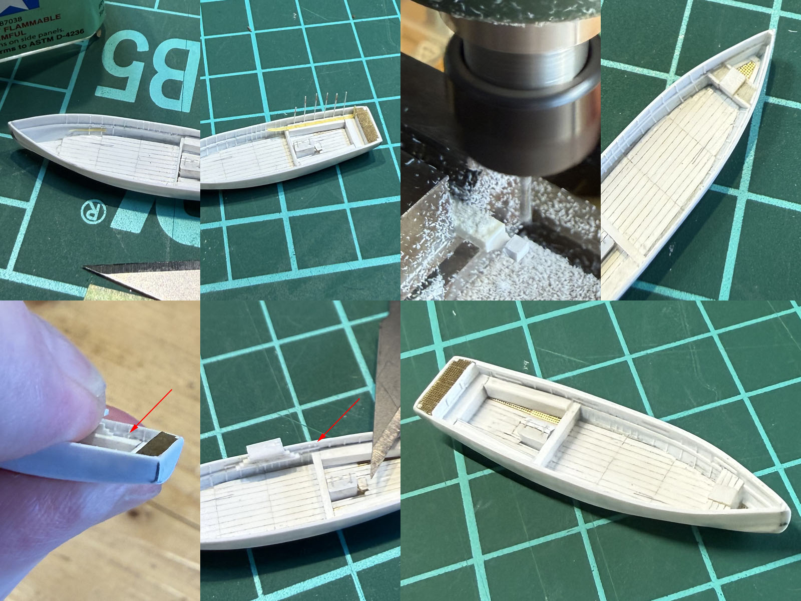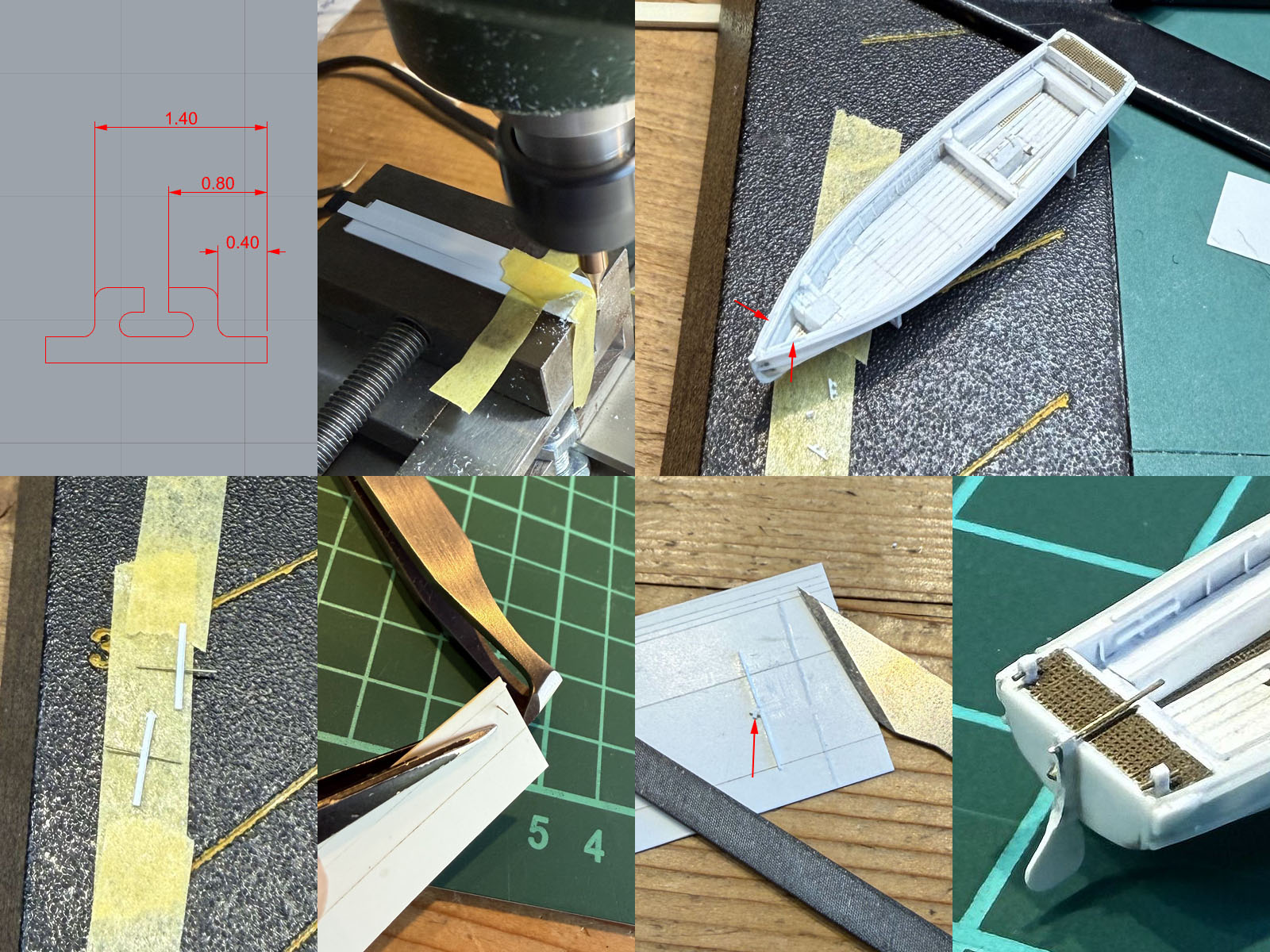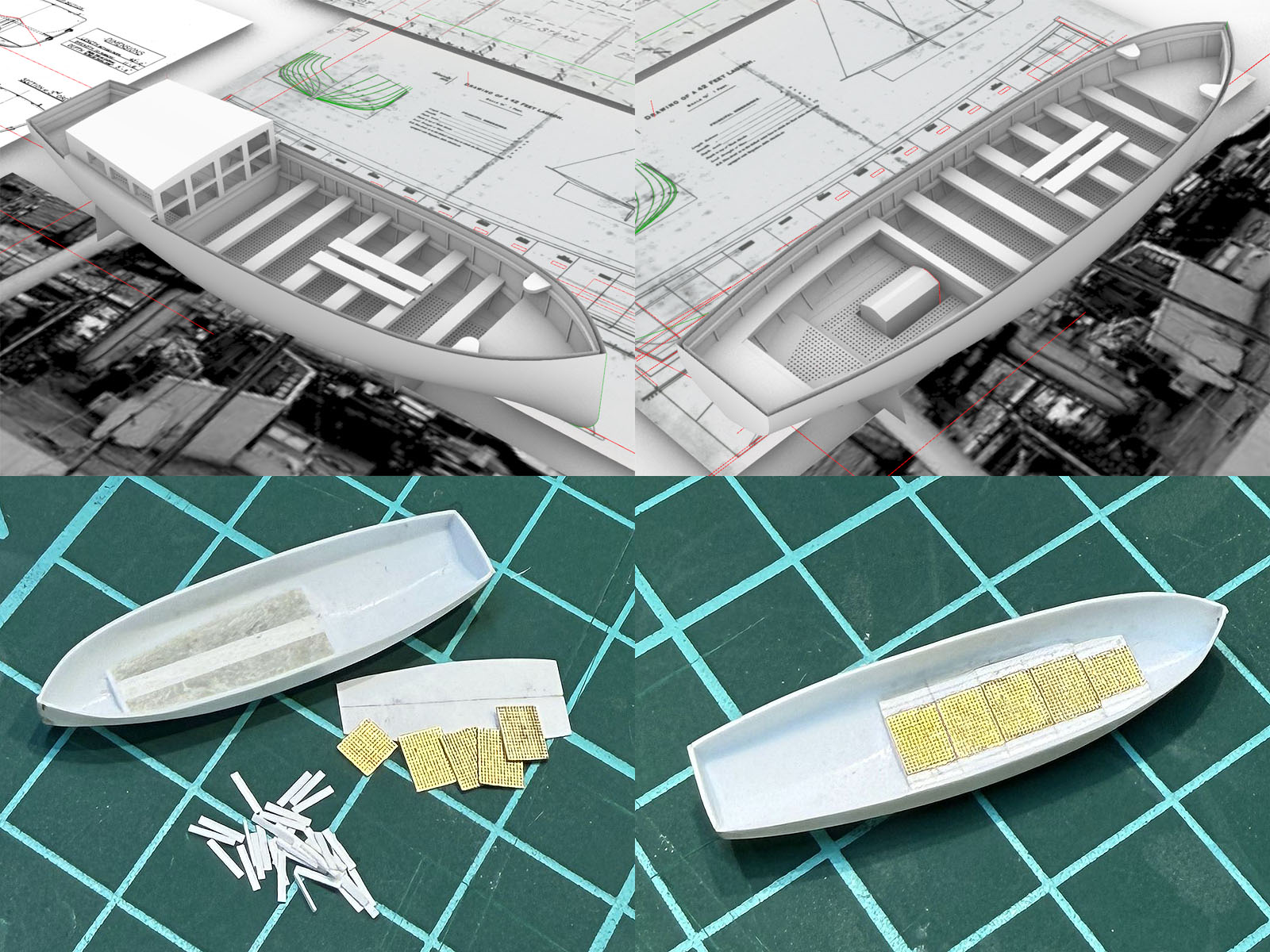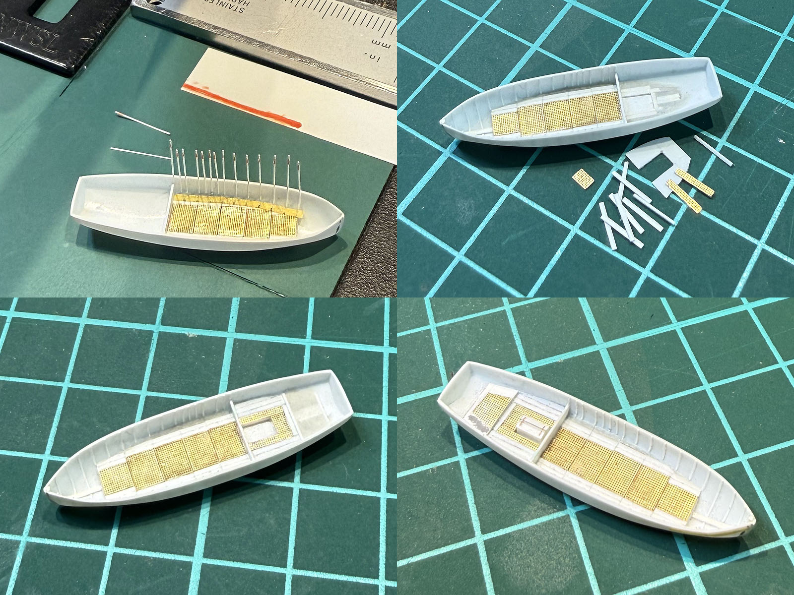
For the aft seating section I though I could make a small insert floor, press into a blob of magic sculpt and all would settle nicely, but that didn't work at all with the insert being too thin and flexible. Attempt one was tossed and the hull cleaned for attempt two. Adding a large keel as a reference as for the forward section is more difficult due to the sloping stern region. So, started with a small strip against the aft of the bulkhead 1.4mm below its top (check with depth probe of the calipers) as a baseline across the section, added a curved keel strip with the right height and at a good angle (check by dryfitting a strip that should be vertical) and topped off with a small plate. Engine location left between some 0.4mm spacer strips, gaps filled off with magic sculpt to form the floor. Strips and more mesh following the same recipe standing by with another bottom plate. The floor for the second section was again made using strips and magic sculpt and finished off with a small floor part; it melted a bit was repaired with putty. The method for the 45ft barge of working downwards from the (solid) seating added first and the floor insert later was easier than working bottom up.
Meanwhile, while the magic sculpt was drying I started with the next boat.
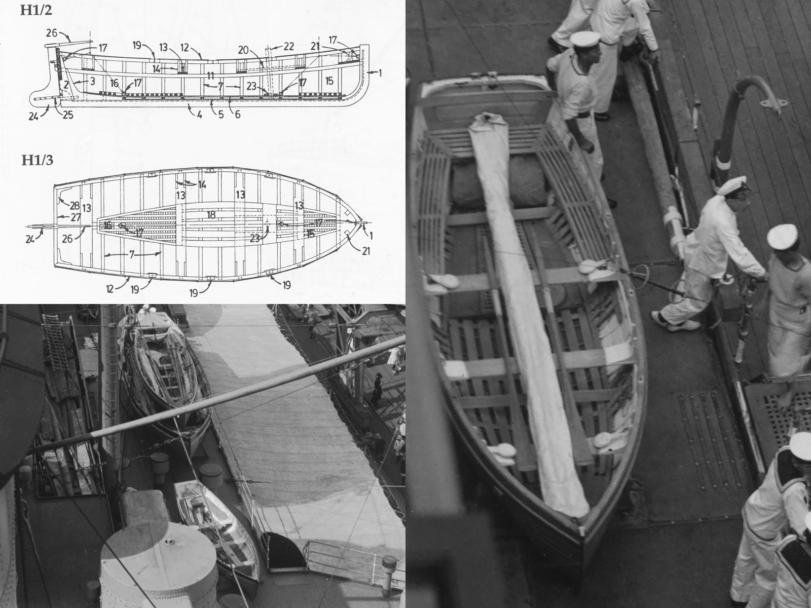
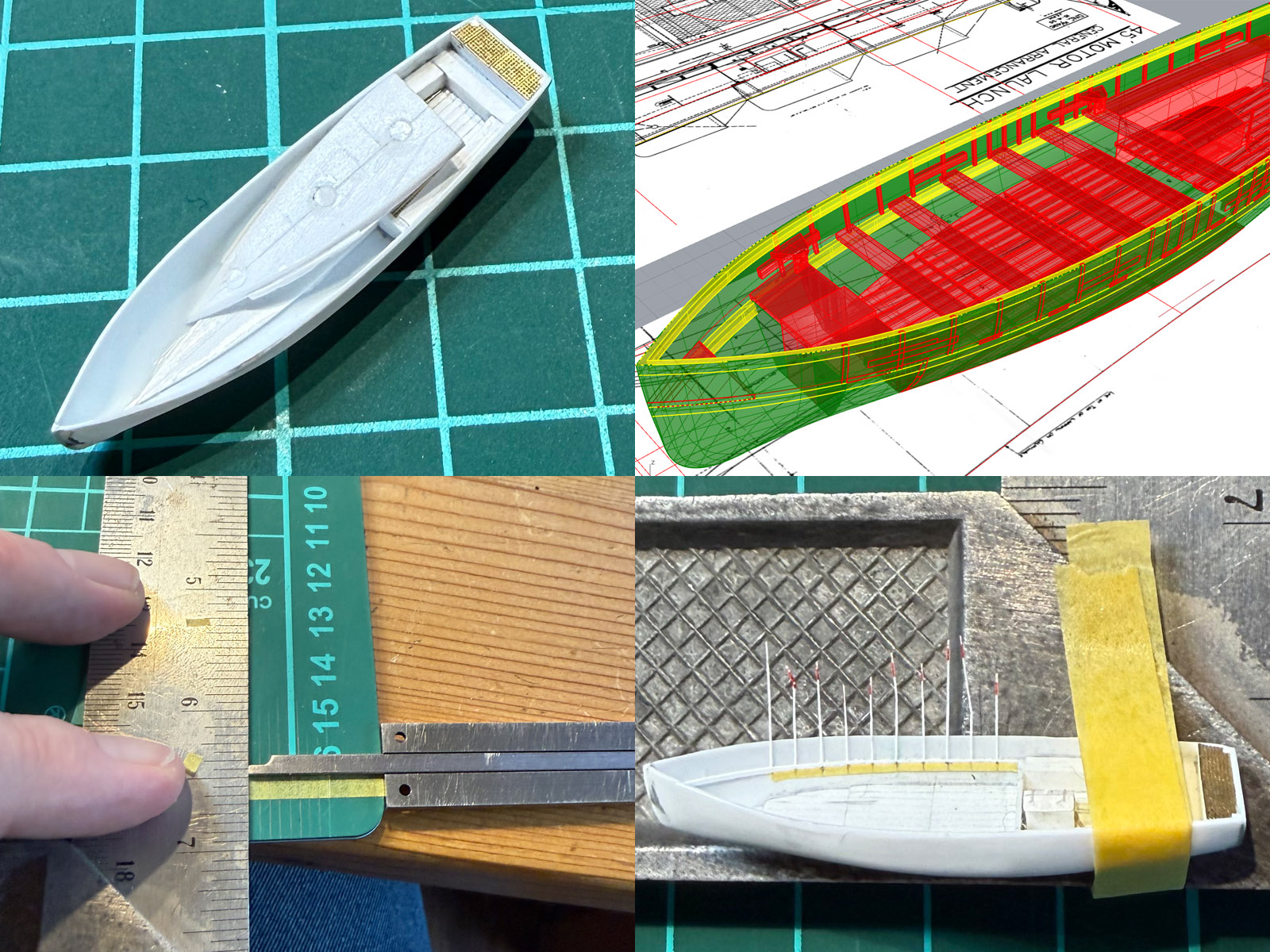
HMS Hood carried two small 16ft dinghy's, according to the AOTS until 1939 when one was replaced by a motorized version---nicknamed the skimming dish---but all three remain visible until late 1941. The sailing dinghy's were stored against either side of the superstructure between the funnels and the skimming dish on the far starboard deck just behind the forward UP launcher. The 16ft dinghy is not as well represented as its smaller 14ft cousin used extensively by the navy for training, see
this page at the BMPT, and of which a drawing by John Lambert was available (L/S/201 while none his work on smaller boats has been reproduced yet I fortunately had a copy). I found a drawing of the 16ft dinghy in the Anatomy of the Ship The Flower Corvette Agassiz,this unsung hero in the series; though no lines were given. Now, the two photographs of the dinghy that I collected, Hood (bottom left) and Nelson, agree well with each other but not so much with the drawing, but it's enough to use these bits of information for new general arrangement. As this is clinker-built the outside might be as time consuming as the inside, but it's only 14 mm long. So how much work could it be.
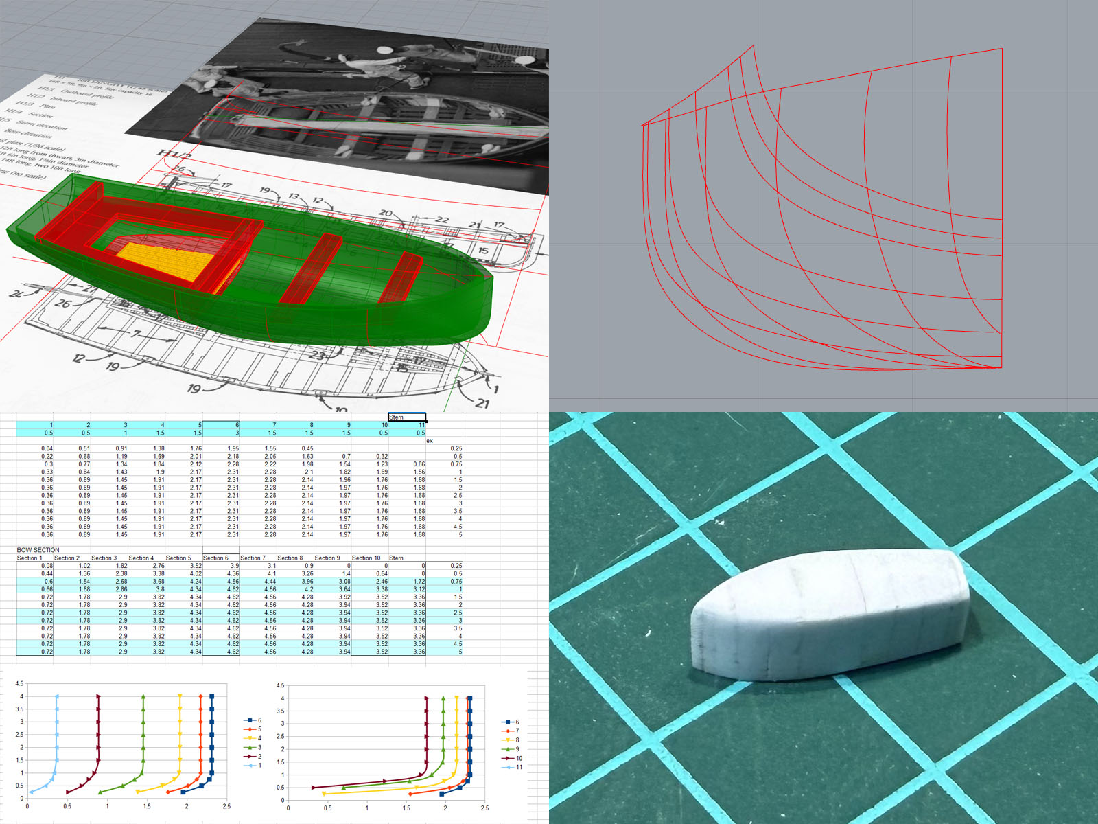
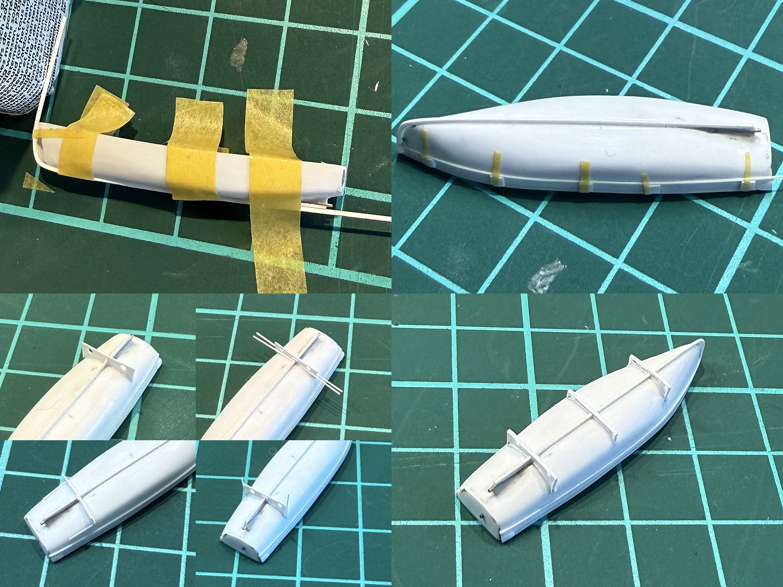
The top view in the first image of the 16ft dinghy shows a slightly different outline compared to the 14ft version, so I simply scaled the lines first to the full beam and then moved the hull lines lengthwise to meet that top view outline (a Lackenby or frame shift). I think the lines of this drawing weren't too well faired; a few waterlines were given but they the bow region was really ill defined. I did some minor refining throwing out the most forward frame and using to top view tangent for all new waterlines and the transom frame was taken from the AOTS drawing. Then an hour or so of “why does Rhino refuse to make a surface” frantic trial and error clicking; this is embarrassing as at work we developed our own hull fairing plugin and we have several CAD engineers specializing in drawing and fairing hulls (far beyond the quality you need for our hobby), I even developed my own spline toolbox to mesh propeller models, but I never got around to acquainting myself with using these tools to get a decent hull. Although it looks ok(ish), the overall quality of the 3D surface is pretty terrible and the inner offset hull has artifacts, but I am not going to print them and it's enough to start the vacuum forming plug. But there still is a lot to learn here if I'm ever going to start building a new large hull. So, the lines in the end look good enough, measurements transferred to open office and a plug made from strips using the default recipe.