Here is the photo I found and scanned at NARA that I didn't recall seeing on the Destroyer History website or elsewhere, it is dated as being taken on 25 July 1943. It is poor (dark and scratches) and is likely why no one has bothered to publish it, but has few crew members in the photo. You can see that the bulwarks are there I think mostly to;
a) Deflect the sea water from the crew and
b) To provide a place to store the trash cans.
Seriously, the port and starboard 20-mm guns are mounted further out than they would be in the typical bulwark tub installed on later ships for three 20-mm guns and where they were are mounted is where the trash cans were originally stored along the railings. There is a color photo in the Destroyer History collection from onboard the Nicholas showing the starboard fantail area on 13 May 1943, and these "semi-circular" tubs had NOT been installed yet. As a matter of uncertainty, I'm not sure that there are three 20-mm guns on the fantail at that time ... looks like from the spacing of the 20-mm visible that there were only two. This is just a guess. Here is a link to a May 1943 photo that shows the same thing, the port 20-mm gun is barely visible ... http://www.ussnicholas.org/43hangfire_02.html ... The Nicholas had a hang-fire incident with her 53 mount at that time and it would not be unreasonable that the 20-mm guns were rearranged to increase the number on the fantail from two to three while undergoing those repairs (they took the 53 mount from the USS Hutchins).
By the way, from another July 1943 photo (on 5 July) it can be seen that these bulwarks go out to the railings. Also, this view sort of shows the inside of the bulwark ... http://www.ussnicholas.org/43topside_09.html ...
You are an endless source of information not to mention a class guy. The photos will help tremendously. I can only hope to know a fraction of what you seem to know.
I have viewed these photos before (not the embedded one of course) on the DestroyerHistory.org website but failed to notice the detail. I guess if it wasn't center focus of the pic, I just clicked on by. Lesson learned, be more attentive to detail.
I have finally decided the time frame for my model of the "Nick". I'd like to portray her as she was during the action at Kula Gulf in July of 1943. So your information has already been very helpful. So here's what I've learned so far:
1) In addition to the original six 20mm's the Nicholas, by July 1943, had four more installed. One atop the pilot house and the other 3 on the fantail as discussed in our recent posts.
2) The paint scheme was Ms-21.
3) There were no depth charge storage racks like those that come with the Tamiya Fletcher kit.
4) The outer two 20mm on the fantail had a semicircular bulwark added.....Thanks to you I can somewhat accurately scratchbuild these.
I'm sure there's alot more that I haven't touched upon, but so far do I have it right?
One other thing......
Thank you very much!
If you're ever in West Virginia let me know, I'll buy you a coffee or a beer, whichever you prefer.
Greg
Greg Willis
Current build: HMS Hood
Kit: Trumpy 1/350
I have a question regarding the placement of life rafts, specifically on the USS Johnston, which I'm building from the Trumpeter Sullivans kit. The only existing photo that I've been able to find (dated in Oct, 1943) shows her starboard side with 3 rafts: one under the bridge, one forward of the midsips 40mm tubs and one between the 20mm's and the K guns. I understand that there were modifications of all kinds made in theater, but what are the odds that the arrangement was the same on the port side?
I was never in the Navy but I was in the military and we always had to keep things looking neat. I would assume that the placements of the life rafts would mirror the the other side unless there was some reason it couldn't (piece of equipment that is on one side but not the other). Not much help but thats the assumption I'm working with for my USS Cushing.
I don't have much to add beyond "Wildspear's" comments. The life-raft locations varied a lot in the Fletcher class based on the builder and/or Navy Yard that worked on them, and generally locations were mirrored on both sides. Actually, if there were any changes, it likely was to add more rafts. So in general, you can only go by the photo(s) you have available to you. I have always wondered if the Johnson was repainted into one of the dazzle schemes, but since there are no photos available of her in the Philippines campaign ... we don't know.
Thanks guys, your responses are pretty much what I was thinking.
Rick, I never thought about the camo thing before, but after going back and looking at the other escorts of Taffy 3, they all wear either Ms 31 or 32 - although the DE's apparently came from the yard that way (according the the shipcamouflage website, anyway). They list the Johnston as wearing Ms 21, but that could just be a result of there not being any hard evidence that she was repainted.
There were several Fletchers that never did get painted in any of the dazzle schemes. Others were painted into dazzle during overhauls, but the ship/Division/Squadron commanders didn't like the schemes and had their ships repainted back to Ms 21 (notably the DesRon 21 ships of the early Fletchers which didn't retain their dazzle scheme past Pearl Harbor). For some reason, none of the DesDiv 84 ships (DD554-557) are documented in dazzle except for the Hailey (DD-556) ... which may have been based on a miss-identified photo ... and I don't recall any photos of her in that scheme. So at this point, don't get too excited about it.
On my 1/96 Floating Drydock plans of the 1945 Sullivans there are a few items I need help on. In the plan view of the after deck house there are six circles on the port side next to the bulkhead labeled "Foam" and on the aft end of the after deck house there is a rectangular shape that's labeled "Foam Pump". I would like to scratchbuild these items but don't know what they are. Can anyone describe these for me or have a photo? Thanks!
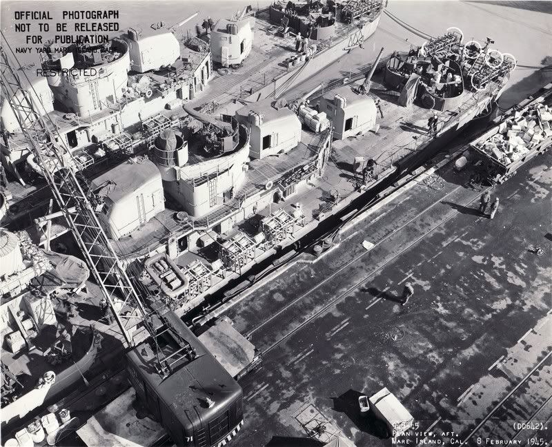
I'm not sure about this, but I think the "foam" is in reference to fire fighting foam. Likely this was in response to the Kamikaze attacks and appears to be a 1945 addition. I have found a few photos of this portside area with what look like tanks (like for oxygen or acetylene) that I can assume are for "foam". I have attached about the best photo I can find on short notice of the Hale (DD-642) on 8 February 1945. Notice that the ship next to her does not appear to have these tanks installed (yet). Also, the Hale only seems to have four tanks, but other ships appeared to have storage for more tanks, but the tanks were not in place. The storage methods varied and since I could find no photos of the Sullivans in this area, I don't know which method she used. The other method I noticed in detail (w/o the tanks) on another ship, used straps attached to the bulkhead in roughly the same area below the 53 mount for six tanks. Since you have a drawing showing where the tanks were located, the location should be solved. I have yet to find what would be the foam pump. Photos for that area are darn near impossible being behind mount 54 and against the aft bulkhead. I can see lots of stuff, but which is the pump is a question mark to me.
Rick, I have to agree with everyone here in saying thanks for your detailed help and photos. I think you are right, the circles represent cylinder tanks. I "Googled" Foam pumps and found a picture of a foam pump on a fire truck that looks like a control box with four hose valve connections on it. I know what you mean about very few pictures of that part of the ship.
Could someone be kind enough to point me to a decent overhead picture or drawing showing the rigging on a square bridge Fletcher? I don't know if its the pictures or my eyes but I just can't seem to make most of it out on any of the photos I have (I have both Alan Raven & Jeff Herne's books) and the drawings I have are all side-on views. Thanks, Pete
Boy this is hard. This is the best photo I could find of the Albert W. Grant (DD649). I love overhead shots of ships and have quite a few. But, when the view is of a whole ship ... the rigging does not show up very well at all. This view of the is overhead and focused on the mid section of the ship ... I hope this helps.
Thanks Rick, thats about as good as any I have. The lines and cables just seem to get lost in the background clutter. I'm basically piecing it together line by line through the photos as I pick them out.
I'm working on the Tamiya 1/350 scale kit and am doing the Radford DD446 as it appears on page 3 of Fletchers in Action. It looks like in that photo that the Radford did not yet have a radar installed. Does anyone know if this is correct? I also have the flagship models PE set but I got it a long time ago and can't find any instructions so I don't know what railings go where. So if anyone can post a pdf file of the instructions I'd greatly appreciate it.
I don't have the Squadron "Fletchers in Action" book. If the photo is of her as delivered, then she may not have had radars installed. The Radford had all the typical radars ... search and fire control ... installed within a week after delivery and definitely by the time she arrived in the South Pacific. In the South Pacific she had two twin 40-mm mounts with the mount between 52 and 53 mount being installed in the lower "tear drop" shaped tub instead of the high superstructure tub (originally intended for the quad 1.1-in. mount) she was delivered with. The other twin was installed on the fantail. She had seven 20-mm guns while in the South Pacific ... two in front of the bridge, one atop the pilothouse, two per side amidships.
Here is a link to a photo of the Radford in the Pacific at Destroyer History Foundation website.
Here is a link at Navsource.org of a photo showing her as delivered (since navsource doesn't allow hot-linking to there website from another ... copy and paste the link into your browser direct or if that doesn't work go to navsource.org and work your way to the Radford (DD-446) page.
Thanks for the reply. There sure are a lot of us getting out our Tamiya Fletchers now that the Trumpeter kit is out. I've had mine probably for 10 yrs. I started it way back but put it aside when I screwed up the depth charge racks that came with the Flagship models PE set. I've decided now to use the kit parts except for the radars, railings and a few other details and I hope I can figure out how to install the railings.
I've gone ahead and installed the PE radar at the top of the mast. Some of the photos in this thread are fantastic, both the pics of the real McCoys and some of the detail shots of the models. I wish I were better at bending the railings esp around the top of the bridge. The stuff is too expensive to buy a replacement set.
My Tamiya Fletcher 1/350's capstan, anchor chain and "other stuff" looks woefully too small. I've done some research and found a good, albeit incomplete feature article here on ModelWarships.com by Steven Spach. In it he uses a lathe to turn the capstan. I don't have access to a lathe much less know how to use it. Does anyone have any ideas on what to use to replace the capstan? I plan on removing everything from the capstan forward with only the deck holes at the very front remaining. Also what are the two things that cover the chains as they go back into the deck called? I haven't even thought about what to use to replace these. Any ideas?
Thanks for any help you guys can give.
Regards,
Greg Willis
Last edited by bocME262 on Wed Mar 19, 2008 9:18 pm, edited 1 time in total.
Greg Willis
Current build: HMS Hood
Kit: Trumpy 1/350


