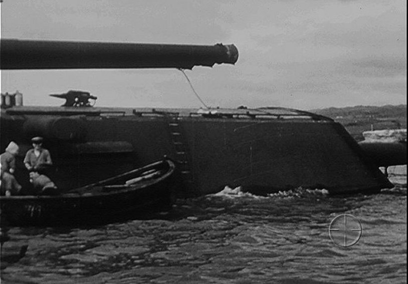
Did the Arizona still have the spotting guns mounted on top of the main turrets on 7/12/41? I am of the belief that they were not , based on this photo, http://www.navsource.org/archives/01/0139008.jpg, but I would like to hear other's opinions.
Thank.
Larry
At 'Em Arizona Fans!
Moderators: BB62vet, MartinJQuinn, Timmy C, Gernot, Olaf Held, Dan K, HMAS, ModelMonkey
-
Jeff Sharp
- Posts: 1056
- Joined: Mon Jan 07, 2008 10:15 pm
Re: At 'Em Arizona Fans!
Hi Larry, yes she still had them. You can see it in the photo you posted, only by that time someone moved it for some reason.
In these picks you can see them in place.
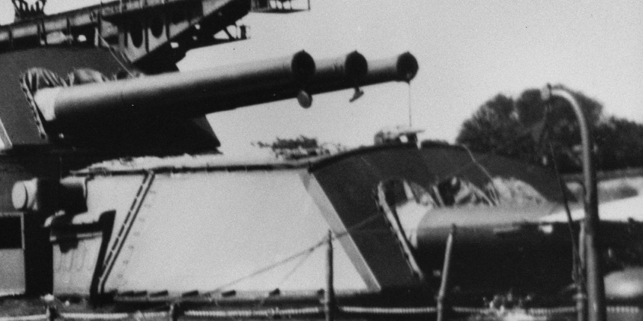
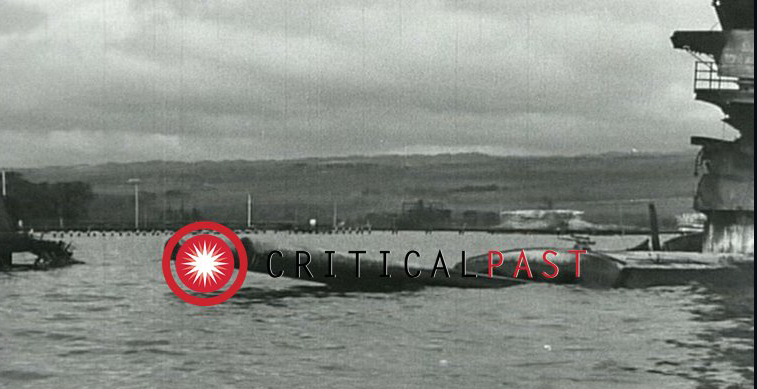
In these picks you can see them in place.
-
lgmccauley
- Posts: 156
- Joined: Mon Apr 13, 2015 2:16 pm
Re: At 'Em Arizona Fans!
Yep, you're absolutely right Jeff. This is why I asked the question, just to be sure.
Thanks.
Larry
Thanks.
Larry
-
harristotle
- Posts: 77
- Joined: Fri Feb 22, 2019 8:21 pm
- Contact:
Re: At 'Em Arizona Fans!
Does anyone have information on how many and what type of ships boats Arizona would have had as standard compliment over the course of 1941?
Michael
Love building and CAD modeling WWII Capital Ships
1/1200 Battle of Hampton Roads diorama in progress
1/1200 1945 USS Pennsylvania CAD model in progress
Love building and CAD modeling WWII Capital Ships
1/1200 Battle of Hampton Roads diorama in progress
1/1200 1945 USS Pennsylvania CAD model in progress
-
mauserbob2
- Posts: 4
- Joined: Tue Feb 12, 2019 8:52 pm
USS Arizona type gun control masts' interiors
I am looking for USS Arizona, Pennsylvania, Nevada etc. type gun control masts' interior pictures, drawings & etc. info. Can anyone help ?
-
Timmy C

- Posts: 12466
- Joined: Mon Jan 10, 2005 6:00 pm
- Location: Ottawa, Canada
Re: USS Arizona type gun control masts' interiors
The spotting tops, most likely.
De quoi s'agit-il?
-
BB62vet

- Posts: 3161
- Joined: Mon Nov 18, 2013 3:41 pm
- Location: Mocksville, NC
Re: USS Arizona type gun control masts' interiors
Good luck with that request - I've NEVER seen any drawings, photos, etc. of the F.C. Platform interiors. Other than the few renderings of the newer Mk. 37 FC Director Interiors, or the Mk. 8/Mk. 13 Rangefinder interior drawings, there just doesn't seem to be anything from the older (30s/40s era) battleship FC tops anywhere. Perhaps Tracy White or Rick E. Davis will read this and comment.
Hope this helps!
Hope this helps!
HMS III
Mocksville, NC
BB62 vet 68-69
Builder's yard:
USS STODDARD (DD-566) 66-68 1:144, Various Lg Scale FC Directors
Finished:
USS NEW JERSEY (BB-62) 67-69 1:200
USN Sloop/Ship PEACOCK (1813) 1:48
ROYAL CAROLINE (1748) 1:47
AVS (1768) 1:48
Mocksville, NC
BB62 vet 68-69
Builder's yard:
USS STODDARD (DD-566) 66-68 1:144, Various Lg Scale FC Directors
Finished:
USS NEW JERSEY (BB-62) 67-69 1:200
USN Sloop/Ship PEACOCK (1813) 1:48
ROYAL CAROLINE (1748) 1:47
AVS (1768) 1:48
-
lgmccauley
- Posts: 156
- Joined: Mon Apr 13, 2015 2:16 pm
Re: At 'Em Arizona Fans!
I have conflicting information as to how many paravanes the Arizona carried in Dec. of 1941. Anyone have any information?
Thanks .
Larry
Thanks .
Larry
-
Jeff Sharp
- Posts: 1056
- Joined: Mon Jan 07, 2008 10:15 pm
Re: At 'Em Arizona Fans!
Hi Larry,
Of all the sources I've seen of her in 1941 prior to the attack including the April 1, 1941 film, the Jan 1941 Puget Sound pic, the November 1941 dry dock pic, and the August 1941 pic. All of them combined show the same thing. There was 1 paravane on the portside #2 barbette and no paravanes on the starboard side #2 barbette. Her plans say she had 3 paravanes on that barbette but I see only 1 in everything I look at.
Of all the sources I've seen of her in 1941 prior to the attack including the April 1, 1941 film, the Jan 1941 Puget Sound pic, the November 1941 dry dock pic, and the August 1941 pic. All of them combined show the same thing. There was 1 paravane on the portside #2 barbette and no paravanes on the starboard side #2 barbette. Her plans say she had 3 paravanes on that barbette but I see only 1 in everything I look at.
-
lgmccauley
- Posts: 156
- Joined: Mon Apr 13, 2015 2:16 pm
Re: At 'Em Arizona Fans!
Thanks Jeff. Everything I have shows the three, but like you, I couldn't find them in any of the pictures available.
Larry
Larry
-
Jeff Sharp
- Posts: 1056
- Joined: Mon Jan 07, 2008 10:15 pm
Re: At 'Em Arizona Fans!
Yeah, I have no idea how the process worked but it seems to me that in order for it to work you put two paravanes in the water, one on either side of the bow. But maybe not. Maybe all you need is one.
-
Rick E Davis
- Posts: 3880
- Joined: Thu May 29, 2008 8:02 pm
Re: At 'Em Arizona Fans!
I have to wonder if there still weren't two-three paravanes onboard, they just are being stowed in a different, difficult to see location. The King Board Mods required several rearrangements.
-
Franz
- Posts: 107
- Joined: Tue Jul 10, 2018 4:44 pm
Re: At 'Em Arizona Fans!
I found the following (I put in quotes) at the below link. It indicates plural paravanes even for warships. I'm betting the other paravanes were probably stored elsewhere while in port.
https://nationalinterest.org/blog/buzz/ ... ared-35842
"Extensive measures and techniques were developed to counteract the mine threat. The minesweeping vessels normally towed two cables behind them, one to each side. Attached to the cables were paravanes, torpedo-shaped floats, keeping the actual sweeps under water. Along the length of the sweeping cable, a series of cutting blades was attached. When a sweep snagged the mooring cable of a mine, it was pulled along the sweep until one of the cutting blades would sever it, making the mine float up to the surface. At this point, the mine would be exploded by fire from cannon and machine guns. On larger combatant ships, paravanes, rigid metal poles mounting the sweeps, were attached to the bow of the ship, severely limiting the ability to maneuver."
Franz
https://nationalinterest.org/blog/buzz/ ... ared-35842
"Extensive measures and techniques were developed to counteract the mine threat. The minesweeping vessels normally towed two cables behind them, one to each side. Attached to the cables were paravanes, torpedo-shaped floats, keeping the actual sweeps under water. Along the length of the sweeping cable, a series of cutting blades was attached. When a sweep snagged the mooring cable of a mine, it was pulled along the sweep until one of the cutting blades would sever it, making the mine float up to the surface. At this point, the mine would be exploded by fire from cannon and machine guns. On larger combatant ships, paravanes, rigid metal poles mounting the sweeps, were attached to the bow of the ship, severely limiting the ability to maneuver."
Franz
-
Jeff Sharp
- Posts: 1056
- Joined: Mon Jan 07, 2008 10:15 pm
Re: At 'Em Arizona Fans!
You would have to believe if there was more than 1 paravane, then logically they would have to be stowed somewhere on the forward deck if not on the #2 barbette. There is not a whole lot of places on the forward deck other than the #2 barbette to put them. The April 1st film gives us great views of the forward deck both port and starboard and there is no paravanes to be seen other than the one on the port side #2 barbette. The boat deck was very crowded with splinter shields and 5" guns. Unless they were stowed by the stack, the boat deck doesn't seem a possibility.Rick E Davis wrote:I have to wonder if there still weren't two-three paravanes onboard, they just are being stowed in a different, difficult to see location. The King Board Mods required several rearrangements.
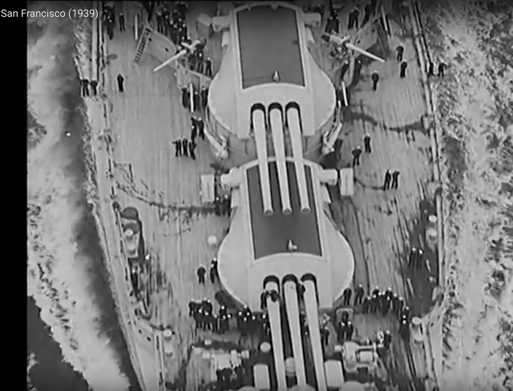
Here is a still of her in 1939 with a paravane on either side of Barbette #2.
April 1, 1941, no paravane on the starboard side barbette:
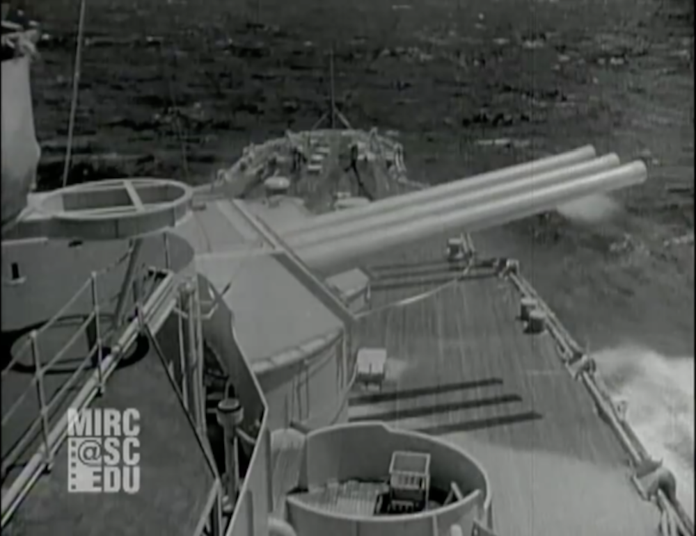
Port side:
I wonder if there was enough room on the front side of barbette #2 to stow a paravane? I don't know what kind of clearance there was behind turret #1.
-
Rick E Davis
- Posts: 3880
- Joined: Thu May 29, 2008 8:02 pm
Re: At 'Em Arizona Fans!
My reasoning for a relocation of stowage of the paravanes onboard USS ARIZONA is based on several factors;
1) At least two paravanes were needed to perform a "standard" sweep operation (a third would likely be a backup/replacement if one was lost in operation and wouldn't need to be stowed close by).
2) In the 8 November 1941 photo of USS ARIZONA in drydock at PHNY, the image isn't the greatest and the paravanes can't be seen, but it is clear that at least on the starboard side of turret #2, two nested life rafts have been located where her paravane(s) use to be located on the barrette.
3) In photos of her sister, USS PENNSYLVANIA, during the 1930's into WWII, she stowed her paravanes on the FRONT of turret #2's barrette.
Cropped view from a photo dated August 1935
Cropped view from photo dated 6 December 1943
I have no idea IF USS ARIZONA relocated stowage of her paravanes to forward of turret #2 on the barrette, or perhaps somewhere else onboard the ship. I'm just about certain she had two or three of them onboard as part of her standard equipment. I don't have many images of USS ARIZONA immediately prior to the Attack on 7 December 1941. A general lack of photos of her and much of the USN Pacific Fleet in the Summer-Fall of 1941 (due to restrictions on photography in general) that causes these questions.
1) At least two paravanes were needed to perform a "standard" sweep operation (a third would likely be a backup/replacement if one was lost in operation and wouldn't need to be stowed close by).
2) In the 8 November 1941 photo of USS ARIZONA in drydock at PHNY, the image isn't the greatest and the paravanes can't be seen, but it is clear that at least on the starboard side of turret #2, two nested life rafts have been located where her paravane(s) use to be located on the barrette.
Cropped view from a photo dated August 1935
-
Franz
- Posts: 107
- Joined: Tue Jul 10, 2018 4:44 pm
Re: At 'Em Arizona Fans!
I just wanted to take a moment out of my Memorial Day to remember all those that have given the full measure in the defense of our great country and especially remember all those those that perished on the USS Arizona.
Everyone have a great Memorial Day!
Franz
Everyone have a great Memorial Day!
Franz
- Attachments
-
-
Franz
- Posts: 107
- Joined: Tue Jul 10, 2018 4:44 pm
Re: At 'Em Arizona Fans!
I finally have a little bit more done on my 1/200 scale Arizona. I'm taking baby steps and trying out some (new to me) techniques. I'll have some other posts on these, but for now I'll start off with a mod to the hull. The big openings at the stern of the hull for the propeller shafts were nothing like what is on the ship's hull. I believe these were done that way for the RC kit. So I pulled out my Dremel tool and cut them off. I then used non-hardening mineral clay flattened smooth on one side to cover the outside of the openings in the hull. On the inside of the hull I poured in casting resin that I mixed together. I think the results came out pretty good (see the attached photos). I still have to do a lot of finish sanding on the hull.
A couple of notes on the mineral clay. It does not contain sulfur or gluten so works well with silicone molds (I use it for sealing and filling in 2 part molds) and with the resin. It also does not dry out. It is a bit on the sticky side and will pick up any debris left on the work surface. It can be re-used multiple times and I store the used clay in a plastic bag. It will not dry out if left out even for days or weeks but will collect dust hence the plastic bag for storage.
Franz
A couple of notes on the mineral clay. It does not contain sulfur or gluten so works well with silicone molds (I use it for sealing and filling in 2 part molds) and with the resin. It also does not dry out. It is a bit on the sticky side and will pick up any debris left on the work surface. It can be re-used multiple times and I store the used clay in a plastic bag. It will not dry out if left out even for days or weeks but will collect dust hence the plastic bag for storage.
Franz
- Attachments
-
- Original opening cut away with a Dremel tool.
-
- Mineral clay being pulled back after resin dried on the inside of the hull.
-
- All four openings filled with resin.
-
- A close up of the filled openings more in focus too.
-
- The box of mineral clay I was using.
-
Franz
- Posts: 107
- Joined: Tue Jul 10, 2018 4:44 pm
Re: At 'Em Arizona Fans!
Ok so the second thing I'm working on is to make replacements for the oval port holes on the hull and I found some bulkhead parts with elongated port holes as well. For this I took up learning how to make molds. I went to the local Hobby Lobby with my wife (we both had the 40% off coupons) and I bought the mold making box and she bought the Resin mix. I then took a few of the parts from the ship that were fairly flat and that had good port holes on them to make the mold. I used a piece of left over Corian type material we had from the kitchen counters for the base and made a mold box using Legos and sealed it with the mineral clay (see previous post). I used Elmers glue to attach the plastic pieces to the Corian base. I then poured in the mold material after mixing in the hardener. For my first mold I was pretty pleased. I did get some very small bubbles appearing at the surface but they are so small that I think once the hull is primered and painted they will no longer be visible. I actually made a resin copy of the parts I used in the mold, but the real purpose was to get good port holes. For this I tried to put as thin a layer of resin just around the portholes of the mold. You can see my results in the below photos.
I used the Elmers glue to attach the parts being molded to the base so they would not float in the mold material. Since the surface was smooth and the plastic parts are smooth they poppped off with out any damage after the mold was made.
Note A hot glue gun can be used to seal the mold box and attach the parts to the base, but the glue can not be re-used (that I know of) so I use the mineral clay and Elmers glue instead.
Note 2 The flashing of mold material covering the backside of the molded parts was carefully cut off.
I used the Elmers glue to attach the parts being molded to the base so they would not float in the mold material. Since the surface was smooth and the plastic parts are smooth they poppped off with out any damage after the mold was made.
Note A hot glue gun can be used to seal the mold box and attach the parts to the base, but the glue can not be re-used (that I know of) so I use the mineral clay and Elmers glue instead.
Note 2 The flashing of mold material covering the backside of the molded parts was carefully cut off.
- Attachments
-
- The Silicone mold material and hardener with measuring cups are in the box.
-
- The casting resin comes in 2 parts mix both equally by volume or weight.
-
- The mold box built with Legos on the Corian base using mineral clay to seal it.
-
- De-molding of the plastic parts once the mold material has cured.
-
- The results of using a fine layer of resin to create good port holes. The front side.
-
- The back side of the port holes. Note how the resin built up around the opening. I plan to sand that smooth.
-
Franz
- Posts: 107
- Joined: Tue Jul 10, 2018 4:44 pm
Re: At 'Em Arizona Fans!
So the final thing I did was to try using polymer clay. It is a plastic clay. It's a bit hard to get malleable but can be worked with once it's warmed up a bit through kneeding. Note that once you get the shape you want you put it in the oven (at the temp it indicates) for about 30 minutes to harden it. I plan to use it to mold some of the electrical boxes and lines on the bulkhead and may even try to make one light that I can then make molds of. I also want to use it for the anchor openings and the correct propeller shaft supports coming out of the hull.
For now I did something simple. I made a punch for the square hatches on the deck using parts of the front bow (not the original, but a molded copy - another story). This gave me a square that was the inside dimension of the square hatch. I combined these with a card stock print of a grate to replicate the grates found in these hatches. See the photo below of the USS Pennsylvania. Note the inside of the hatch is painted white and has what looks like a vent pipe coming out at the back left side. I believe the grates were used to allow for ventilation and to keep anything from the deck accidentally finding its way down the hatch. They would be popped out when using the hatch.
The photo of the deck shows one press fitted in. I did not get the clay thin enough to show a grate on deck, but it works great for press fitting in from below. Once in the hatch you can't tell how thick the plastic grate is. I decided on using card stock to reduce the size of the print to close to the scale (I left it a bit over sized so I could cut it flush with the plastic grate) I glued the card stock image of the grate to the top of the plastic clay grate (after it was hardened in the oven) using super glue. I press fit the grate in from the bottom side of the bow deck. I still need to add the vent pipe to complete the hatch detail.
I decided to try this first as it seemed simple and strait forward and as I plan to leave all my hatches open this will add some detail to the square ones.
For now I did something simple. I made a punch for the square hatches on the deck using parts of the front bow (not the original, but a molded copy - another story). This gave me a square that was the inside dimension of the square hatch. I combined these with a card stock print of a grate to replicate the grates found in these hatches. See the photo below of the USS Pennsylvania. Note the inside of the hatch is painted white and has what looks like a vent pipe coming out at the back left side. I believe the grates were used to allow for ventilation and to keep anything from the deck accidentally finding its way down the hatch. They would be popped out when using the hatch.
The photo of the deck shows one press fitted in. I did not get the clay thin enough to show a grate on deck, but it works great for press fitting in from below. Once in the hatch you can't tell how thick the plastic grate is. I decided on using card stock to reduce the size of the print to close to the scale (I left it a bit over sized so I could cut it flush with the plastic grate) I glued the card stock image of the grate to the top of the plastic clay grate (after it was hardened in the oven) using super glue. I press fit the grate in from the bottom side of the bow deck. I still need to add the vent pipe to complete the hatch detail.
I decided to try this first as it seemed simple and strait forward and as I plan to leave all my hatches open this will add some detail to the square ones.
- Attachments
-
- The square hatch is to the lower right of this picture of the USS Pennsylvania. The only shot of the grate I could find with this angle showing what is inside.
-
- A close up of the square hatch showing the grate and the vent tube in the upper left of the hatch.
-
- The stamp I created of the square hatch from parts of a resin copy of the bow deck.
-
- A photo of a hatch grate I found online. I modified this photo to get rid of the tag and glare. I used microsoft paint to do this.
-
- The reduced multiple copies of the grate photo using page set up to reduce the size. Printed on card stock.
-
- The polymer clay (after hardening) I used an exacto blade to cut them lose (but not popped out) and glued a grate photo to the top. I thin popped them out and cut off the excess of the photo grate.
-
- This is what the grate looks like in the hatch. All it's missing is the vent pipe. Note this was dry fitted so will be removed till it'
s ready to be put in permanently.
-
- This is the polymer clay I used. I picked it up at Hobby Lobby.
-
Franz
- Posts: 107
- Joined: Tue Jul 10, 2018 4:44 pm
Re: At 'Em Arizona Fans!
David,
I saw your thread and was very impressed. If I just had the skills!! That's why I'm just taking baby steps for now. I have not attempted a model in quite a few years and don't want to ruin this one. So my hull mods will not entail very many changes to the hull dimensions themselves. The points were the propeller shafts exit the hull were just to obvious to ignore. Using the mineral clay over the opening allowed the resin to dry flush with the hull.
Franz
I saw your thread and was very impressed. If I just had the skills!! That's why I'm just taking baby steps for now. I have not attempted a model in quite a few years and don't want to ruin this one. So my hull mods will not entail very many changes to the hull dimensions themselves. The points were the propeller shafts exit the hull were just to obvious to ignore. Using the mineral clay over the opening allowed the resin to dry flush with the hull.
Franz