Page 20 of 29
Re: 1:75 diving support vessel Well Enhancer
Posted: Sun Oct 06, 2013 11:03 am
by tweety777
Update:

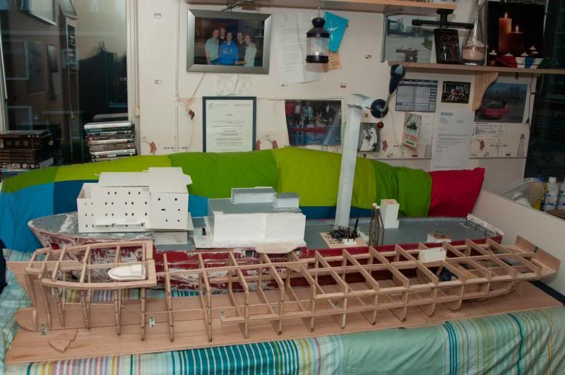
The bottom part is finished for the time being, painting will be done later on.

This is what it will look like when operational.
Greetings Josse
Re: 1:75 diving support vessel Well Enhancer
Posted: Sat Nov 30, 2013 5:22 pm
by tweety777
Update:

As I didn't manage to get the controls working but was eager to continu the work I decided it would be good to continu working on the superstructure.
The side wall of the wider part of the superstructure had been cut out of the rectangular piece of styrene from which I made the rest of the side wall I only needed to cut the windows out in order to be able to place the wall.
Here I taped the new wall to the other wall (the nice thing is that for once the new wall matches perfectly with the wall on the other side.

Used my Maglite to light the windows so I could mark their locations.


As the way of drawing the windows descriped above is not quite accurate I took a precision tool which is precisely 90degrees in angle to draw a straight line where the edge of the window should be.

This is the inside of the new bulkhead with the windows now cut-out.

At last the glue clamps were also used as I decided that I could just as well place the bulkhead as I was already on it anyway.
Hopefully I'll make the connecting wall and the deck under it tomorrow.
Greetings Josse
Re: 1:75 diving support vessel Well Enhancer
Posted: Sun Dec 01, 2013 9:10 am
by tweety777
Update:

Continued with building the front bulkhead for the wide part of the superstructure.
As you can see I made a hole for a door as I want to have this door open to make the model look more alive.
Behind this hole I will build a hall which will be painted in the colours of the interior but will not be all to detailed as 1 can hardly see anything inside.

Also placed the bottom making the next thing on the to-do-list making the platforms.
When the platforms are done I'll start correcting the dive area and then I'll probably add the platforms on the dive area too.
When the dive area is done I can start making the interior for the superstructure and the wheelhouse and quite some working functions and then this beast will start to look like an operational model at last!
Greetings Josse
Re: 1:75 diving support vessel Well Enhancer
Posted: Mon Dec 02, 2013 6:36 am
by tweety777
Update:

Added a stiffener to the superstructure.

Building the first platform.

The great yellow inspector was back on board again!

Overall view with Tweety as special guest.

Tweety attempted to look inside and to unsharpen the edges...

Quick inspection of the rear wall.

"Where are those magic controls? I want to test them!!"

"Let's see if I can scratch build some exhaust pipes out of this material..."

Unfortunately I didn't manage to get Tweety on the joystick but I think the idea will be clear.
Greetings Josse
Re: 1:75 diving support vessel Well Enhancer
Posted: Mon Dec 09, 2013 4:14 pm
by tweety777
Update:

Added a stiffener in the superstructure.

Platform with its edges.

More stiffeners.

Greetings Josse
Re: 1:75 diving support vessel Well Enhancer
Posted: Fri Dec 13, 2013 8:44 am
by tweety777
Update:

The tools that I use to make the platforms and a platform ready to be cut out.

The first edges are placed on the new platforms.

Added a stiffener to the rear wall as it was still a little bit weak.


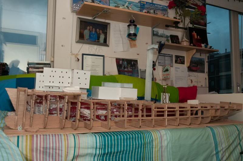
If you take this image and go to a lower angle of view you'll get the image I see when I open my eyes while laying in my bed.
I'd better not stretch out all too much because I could very well hit my boat when doing so...

Lots of stuff going on here.

Greetings Josse
Re: 1:75 diving support vessel Well Enhancer
Posted: Mon Dec 23, 2013 1:01 pm
by tweety777
Today I started sanding the hull again, this time as a preperation for the depthmarkings, ships name and other markings together with the bilge keel, water inlets and the ballast tanks.
Whilst sanding the hull in such a manor that the hull shape would be corrected as well I quickly found out that the hull needed way more adjustments to get the correct shape then I realized at first.
This resulted at first in some small holes where I simply sanded away all the hulls material.
When I got to the stern I noticed I could bend some parts of the hull really easy and on further investigation I discovered that in those places the polyester simply hadn't got a hold on the duct tape.
If you think it's bad to have duct tape on your hull it's about to get worse...
I discovered I had cut some corners thinking the polyester would keep the water out so in order to get to the next fase earlier I used a piece of duct tape some 10cm long and some 3cm wide instead of planking...
Now realizing how bad this was I removed the duct tape leaving this big hole behind.
At this point I started thinking that it might very well be better to build an entirely new hull instead of keeping improving a poor hull...
This off course will take quite some time to do but if I use the learned lessons it will certainly do the model good.
By now I pretty much decided that this will be the course of action.
That means that the work on the superstructure will continu whilst I start designing the construction of the new hull.
The new hull will be much improved when it comes down to room inside meaning no watertight bulkheads, just open frames.
I will build new bow thrusters myself which will be placed in a bath of resin to ensure watertightness.
There will be ballast tanks and a good and firm spot for the batteries.
Whilst building the hull I will also incorporate the bulwarks by making molds for the bulwarks so they will be 1 strong part with the hull to reduce the chanse of bulwarks breaking free.
All in all the new hull will be a huge improvement, especially on the inside, over the current hull.
While I'm at it I might also find myself building a new tower, dive area and rear funnel.
Greetings Josse
Re: 1:75 diving support vessel Well Enhancer
Posted: Mon Dec 30, 2013 10:54 am
by tweety777
Small update.
Yesterday I entered the frames into Delftship and after that I exported it to ACAD so I can start designing the shape on the inside.
I still need to adjust the bowline as I now got a line in quite a random way, only having a correct frame line about half way through the bulb running through to the foc'sle deck.
Quite some ideas have crossed my mind up to this moment and a lot of improvements have come forward from thinking it all through.
For starters I use 1 longitudenal girder as edge to glue the polycarbonate fake deck to, 1 longitudenal girder below it which include the platform in the stern engine room (which is also to rest on the frames which will be shaped just to do that) and then 1 more longitudenal girder below quite possibly including even more platforms.
In the bow I might well add 1 or 2 more longitudenal girders to both ensure a straight fit and hull and to make it easier to fit the decks to the hull.
The ballast tanks with most of the water related gear (pumps for the fire monitors, cooling water and flushing of the anchors) will be placed under a polycarbonate cover to keep leaking water away from the electronics.
In the bow I will reserve some room for a PCDuino with a powerful WiFi antenna and it's needed parts.
The WiFi antenna will be placed in the bow to keep it as far away from the 2,4GHz transceiver as possible to lower possible interference.
The wiring will be placed inside 2 PVC tubes to make the inside look neat and tidy.
On to the superstructures, which will also be improved over the current versions.
I will start with the build style I want to use on Seven Atlantic, meaning that all decks and walls will be build outside the model and will be placed when the last layer of paint has fully dried with all the details in place.
The superstructures will fit perfectly over an edge which is to ensure a watertight hull.
This means that the covered walls around the dive area and between the dive area and the main superstructure will be placed when both decks and all the walls have been glued together.
If someone has suggestions about the above or some other advice I'd be more then happy to read it.
Greetings Josse
Re: 1:75 diving support vessel Well Enhancer
Posted: Mon Dec 30, 2013 5:08 pm
by tweety777
Hi all,
Today I started to plan where the ballast tanks should be, thinking at that point that ballast tanks between 4 frames would be enough as that was the conclusion drawn from the calculations for Seven Atlantic.
When I started calculating for Well Enhancer I quickly found out that the calculations for Seven Atlantic had been off by a long shot.
A few tanks in between some frames?
Not a chance, that would be lighter then a lightweight superstructure...
Instead I've now decided that I would use a total of 4 ballast tanks, each 5 frames long and ending to the keel and on the other side the outer hull.
The tanks will be L-shaped with the double bottom part being 3cm high inside the tank and the high part is to be 2cm wide, the total height being 11cm which means that I will have to pump the water in as it will not get that high up by itself.
This does mean that the frames will not be visible at all when the tanks are finished leaving this huge part of the hull with a hold suitable for containers...
The downside is that the PVC tubes which I first wanted to place through the frames will now be placed against the tank walls.
The frames inside the tanks will be fitted with holes to allow water to pass through.
Greetings Josse
Re: 1:75 diving support vessel Well Enhancer
Posted: Fri Jan 03, 2014 5:26 pm
by tweety777
Update.
Today I started drawing the first 14 of 21 frames onto the first sheet of plywood filling it entirely so I tomorrow I can start sawing and drawing the other frames.
I had hoped that I would be able to use my software to develop the shape of the frames but something went wrong while exporting and it kept going wrong.
For the aft 9 frames the problem was not too big so I could work around it but then the lines started to go too high up in a wrong shape causing the entire line to be useless.
This problem is now solved by using the paper linesplan and taking the frame nearest to where I want a frame and cutting that out and then draw it onto the wood.
Because of the thickness of the frames I have had no problems whatsoever finding a frame inside the region which is covered by the frame.
When I was making my walk again a though came to mind that my ballast tanks might well be placed in the part of the ship where the real ship has her engine rooms.
At first that doesn't appear to be problem but then I realized I wanted to have water coming out of cooling water outlets and those are placed between the front and rear walls of the engine rooms.
That means that all cooling water outlets might well end up inside the ballast tanks.
A solution for this problem came as quickly as the problem had came to mind, a tube with a 90 degree angle in it would be placed inside the ballast tank to have it exit the tank either in the fwd bulkhead or the rear bulkhead so that it won't get in the way of the removable top plate with it's connected side walls.
The reason for having the inner plates of the tanks removable is that it allows me to clean the tanks which could well be very important due to the fact that I usually find myself ballasting her in water that are hardly deep enough for the model to sail at her normal depth.
That means that filling the tanks might well mean pumping mug in the tanks as well.
Beside the mud matter there is also the point of having all water in the tanks vaporize when the tanks are opened whilst it would still be inside the tanks when the tanks remain closed.
Greetings Josse
Re: 1:75 diving support vessel Well Enhancer
Posted: Sat Jan 04, 2014 4:52 pm
by Ticonderoga
Hi Josse,
I have sent you a PM
Regards,
Andrew
Re: 1:75 diving support vessel Well Enhancer
Posted: Sun Jan 05, 2014 6:05 am
by tweety777
Update:

These frames here are still to be sawed out.
After the first 4 frames (of which 2 are complete frames, no weight savings to be taken out) I decided it was best to first saw the frames to the correct shape (with a little margin as the completed construction will be sanded to make it ready for the hull plating) and then take all the frames again and saw the inner parts out to make room for all sorts of things.
Up to this point I used the eletric saw only but I'm thinking about using the manual saw later in the process as well.

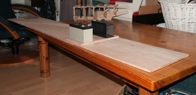
Lots of trash material and the first 13 frames and the keel that has been sawed out.
Yesterday evening I decided to put the new keel alongside the old model to see what is was going to look like only to discover that the new keel was 10cm shorter then it's supposed to be.
In this photo one can see a little plank of wood in between the 2 pieces of keel, this plank will give the keel the correct size by means of putting it in between the 2 pieces of keel.
Greetings Josse
Re: 1:75 diving support vessel Well Enhancer
Posted: Mon Jan 06, 2014 11:08 am
by tweety777
Update:

All the construction parts have been made!!!!
After that I also made room for the new hull to be build in my room though it appears that there is very limited room for the new model.
At this point all construction is rough in shape, I did this on purpose as I had already planned that I would sand the entire construction to make it all fit perfectly and to give it precisely the correct shape and to angle the edges where needed to increase the glueing surface for the hull plating.
Tomorrow I will start preparing the construction to be made to 1 entire hull by means of making small inserts that fit as precise as I can achieve into the corresponding insert in the other construction.
I'm hoping I can finish that job tomorrow but I certainly won't hurry as I want nothing less then a real good result so the bar is set high!
I'm now using a system of building for about 1 hour and then I do anything else mostly to clear my head so I will be looking at the model with fresh eyes to prevent hurrying and the associated result.
Greetings Josse
Re: 1:75 diving support vessel Well Enhancer
Posted: Tue Jan 07, 2014 10:14 am
by tweety777
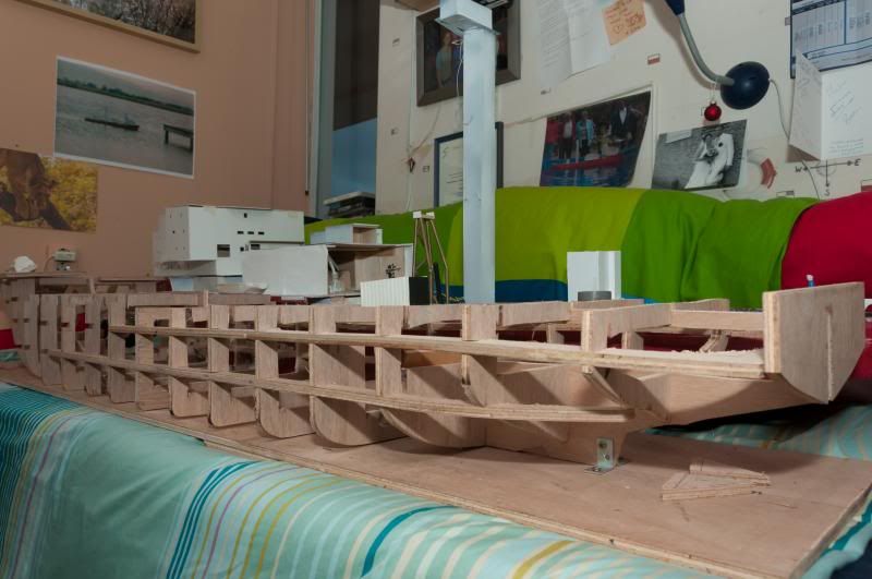
Update:

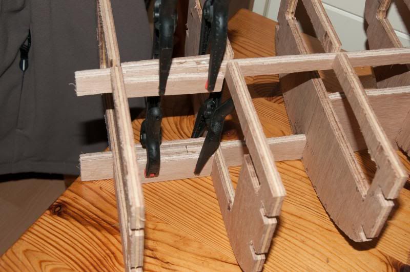
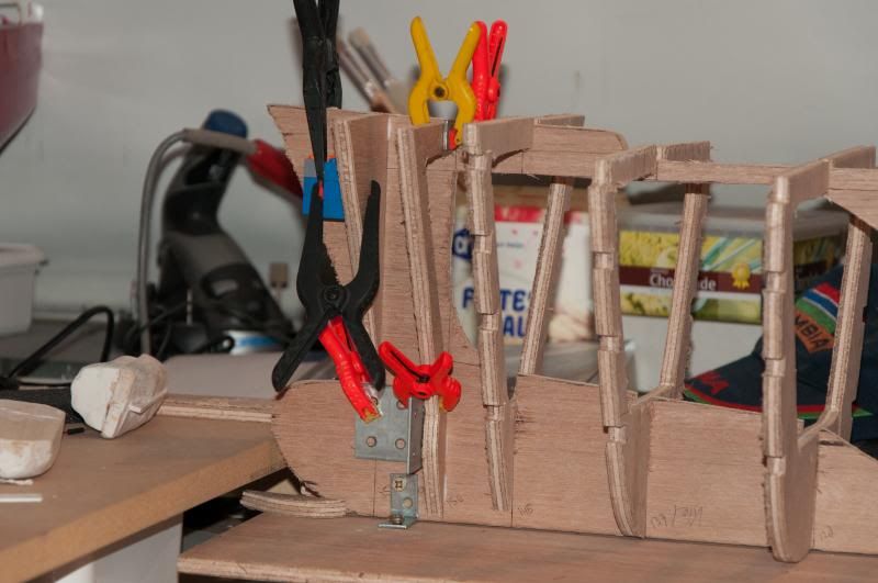
After having sawed out the inserts I dryfitted the frames on the keel, glueing will only happen when I'm confident that I will get a perfectly straight full by doing so.

Starts to look like a hull.

The fitting of the top side of the keel between the frames will need some work but other then that the hull is still straight!!!!

Old versus new.

It appears in this photo that foc'sle deck is too long on the new hull so I'd beter check it out, it's no big deal at this moment as long as I deal with it now.
Today I've only been working on the frames and the keel, I will draw the inserts on the longitudenal girders tonight so I can finish the work tomorrow.
For taking out the inserts I found a great team: the electric saw and a manual saw for sawing shapes.
First step is to make the cuts on the sides of the insert with the electric saw which is a nicely quick process and then one takes the manual saw and move it sideways through the cut and without turning the saw.
Greetings, a very happy and satisfied Josse
Re: 1:75 diving support vessel Well Enhancer
Posted: Tue Jan 07, 2014 4:52 pm
by tweety777
Update:

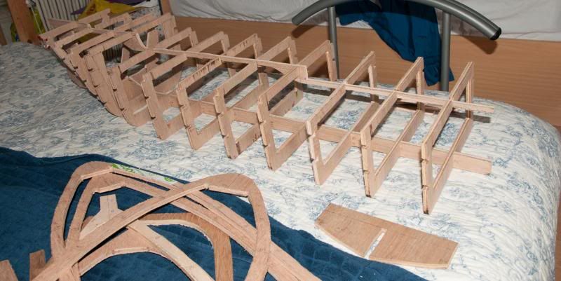
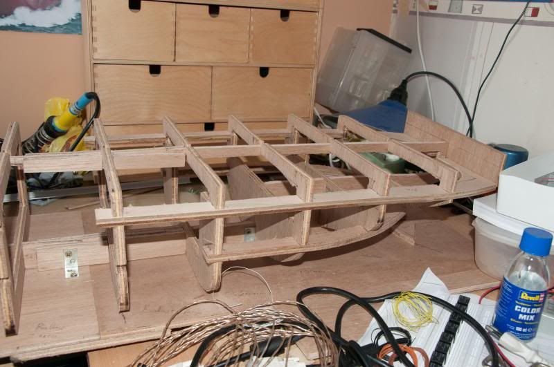
A days worth building.
So far I'm quite pleased with the result, it's looking faaaar better then the first hull did.
Greetings Josse
Re: 1:75 diving support vessel Well Enhancer
Posted: Wed Jan 08, 2014 6:09 am
by tweety777
Update:
Someone adviced me to use a building board albeit mostly to use the lines that are to be drawn on it as a reference to check if the hull indeed is straight and true.
Here I'm glueing the 2 pieces of building board together, due to the work plates on my desk the connecting plate will not cause the hull to be out of level.
When all the frames are being glued to the hull I will check the fitting of the frames which do not touch the building board by shining a flashlight over it as the edge of the shadow will show where the frames is.
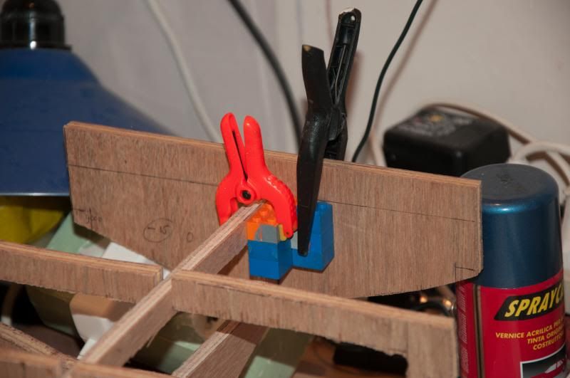
The loose pieces of hull are being connected.
Finished making the inserts on the frames.
The next step will be placing the keel and the frames on the building board so I can check the locations of the frames drawn on the longitudenal girders so I can start drawing the inserts on those as well.
Greetings Josse
Re: 1:75 diving support vessel Well Enhancer
Posted: Wed Jan 08, 2014 4:53 pm
by tweety777
Update:
Glued the stern plate to the hull.
The most important reason for this is that I use this as a reference from which I can start measuring.
The keel has been fixed to the building board by means of metal L-profiles with screws in them.
The keel turned out to be about a millimeter off somewhere in the middle but that has now been fixed and when the longitudenal girders have been placed I won't even notice it anymore.
Glued the first parts of the front most frames to the keel.
Greetings Josse
Re: 1:75 diving support vessel Well Enhancer
Posted: Fri Jan 10, 2014 10:23 am
by Neptune
That's a very brave decision you took. One that will slow down your completion time and cost you something. But in the end, I'm sure it will pay off! The start looks great! I took the decision not to use a build board because the bottom was flat, yet I still regret that decision!
My hat's off to you, since very few people would have the courage to decide to start all over on the hull! Your dedication is awesome.

Re: 1:75 diving support vessel Well Enhancer
Posted: Fri Jan 10, 2014 10:43 am
by tweety777
Hi Neptune,
Thanks for the compliment!
I really had come to a point where I realized that continueing with the old hull would not give me the result I wanted to have, even after years more labor on the hull and as I've made mistakes in measuring all sorts of things were lined up with incorrectly positioned things and the list of problems just kept growing so with no hard or negative feelings I decided I would start over and do it really very good this time.
My building board has also already paid out it's use, the keel turned out to be bended by only a millimeter or so but I wouldn't have seen that with my naked eyes but thanks to the line I drew on the building board I was able to see the bend.
Also for aligning frames it proves to be very useful, I'll use it on future models as well.
Greetings Josse
Re: 1:75 diving support vessel Well Enhancer
Posted: Fri Jan 10, 2014 11:29 am
by tweety777
Update:
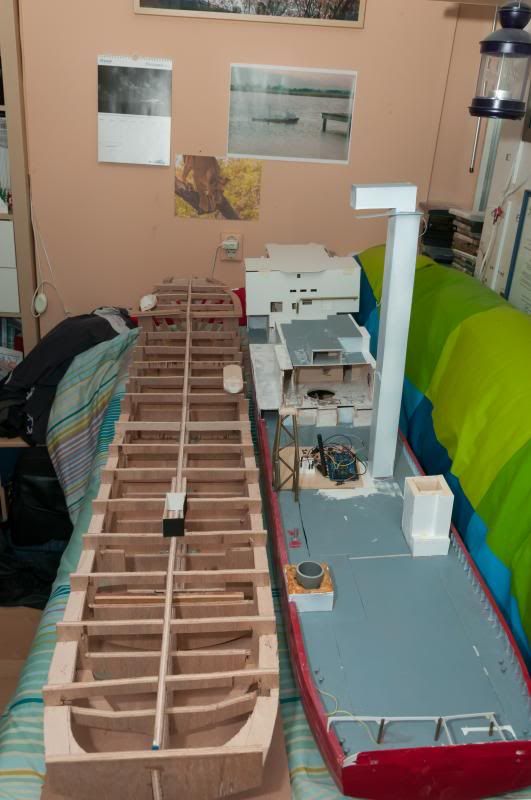
Placed the aft most section of the longitudenal girder as a dryfit.
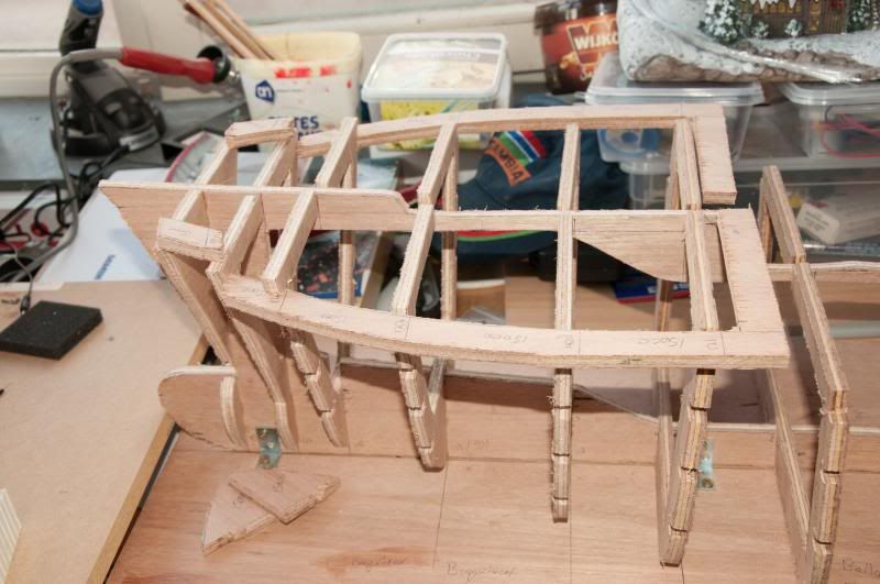
There is still a lot that needs to be done to make the top most girder fit, unfortunately 1 of the frames which has been glued in place yesterday evening didn't have enough room for the glue causing it to stay too high.
I will fix this problem with wooden planks.
Even though I only glued a few frames to the keel today the dryfitted longitudenal girders make the hull much more stiff already.
Unfortenatly I did break the forward section of the lowest girder.
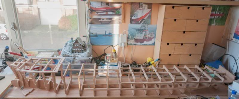
I'm thinking about not using the lowest girder all the way to the bow, just the parts that can be seen in this photo as 2 girders at the stern make it already such stiff and the bow has the honor of having the full 4 girders so 1 less doesn't seem to be all that much of a problem.
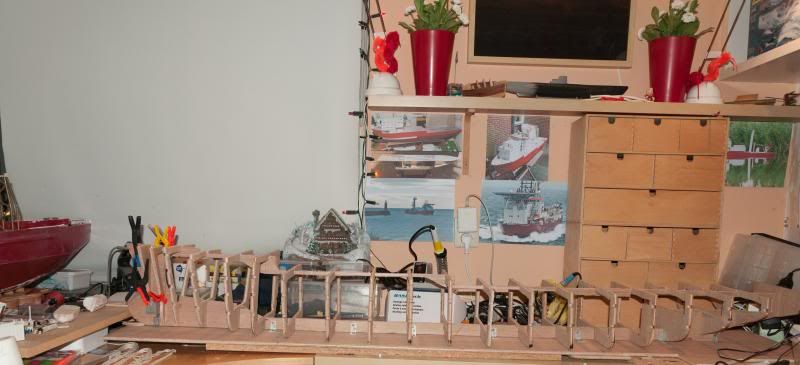
Placed the old and the new hull alongside eachother to show the progress against the benchmark which the new hull must and will improve by a huge difference.
I still can take these kind of photo's as I'm not glueing anything at all at the moment so a little bending doesn't matter should that even be possible with the keel screwed to the building board in 7 places.
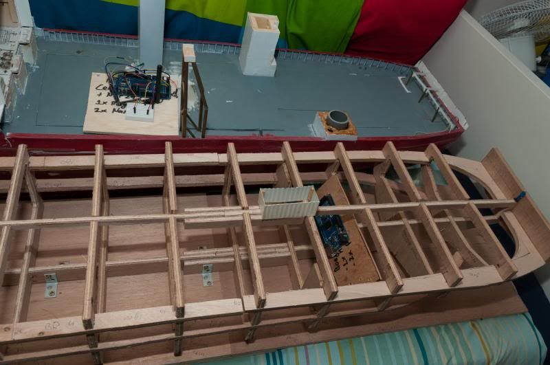
The Arduino shows the location where it will later be placed along with the electronics to which it will be connected.
Originally I intended to place it on the platform that will be placed just above where this Arduino is now but there appears to be too little height for that.
The shape starts to be visible and it's looking good!
That's the last one.
Greetings Josse