And the cranes are now mostly done. Although Nevada and Oklahoma are sister ships, and Arizona is very similar, their boat cranes are all different. Nevada and Arizona are the most similar, but post supporting the crane is shorter on Nevada. Oklahoma has the shorter post as well, and the bracing strut connects to a lower part of the crane arm. The cranes on Oklahoma (left) and Nevada (right) also had some boxes and such near the top, which I may add later.
Mike
Battleship Row in 1/700
Moderators: BB62vet, MartinJQuinn, JIM BAUMANN, Jon, Dan K
-
mconnelley
- Posts: 249
- Joined: Sun Feb 07, 2010 8:13 pm
Re: Battleship Row in 1/700
I thought that I had already posted a brief review of the Hi-Mold USS Arizona kit, but hadn't. Without further ado, here it is.
The kit is unique in the Hi-Mold line of kits in that 1) it's cast in a pale green resin (the others are light gray) 2) the resin parts have full spues rather than just casting blocks and 3) there are no cast metal parts. Also, the tripod masts are cast in resin and they don't just tell you to use some rod stock.
The kit is unique in the Hi-Mold line of kits in that 1) it's cast in a pale green resin (the others are light gray) 2) the resin parts have full spues rather than just casting blocks and 3) there are no cast metal parts. Also, the tripod masts are cast in resin and they don't just tell you to use some rod stock.
- Attachments
-
-
-
-
mconnelley
- Posts: 249
- Joined: Sun Feb 07, 2010 8:13 pm
Re: Battleship Row in 1/700
Here's a closer look at the hull and turret castings. The kit also comes with turned brass main gun barrels.
- Attachments
-
-
-
-
mconnelley
- Posts: 249
- Joined: Sun Feb 07, 2010 8:13 pm
Re: Battleship Row in 1/700
Here's a look at the instructions.
Overall, a really nice kit and far better than the injection plastic kits I've seen of Arizona. Some things that I don't like are:
1) No photo etch. Some items like the catapults, cranes, and yard arms would be much better in photo etch. The other Hi-Mold kits have a small PE fret, so I'm not sure what happened here.
2) The main gun barrels have too much separation between them. I replaced them with 3D printed versions.
- Attachments
-
-
-
-
-
mconnelley
- Posts: 249
- Joined: Sun Feb 07, 2010 8:13 pm
Re: Battleship Row in 1/700
Here are a few pictures of the main mast for USS Arizona. It's just resting on the deck, so don't worry about it not being plumb. It was quite tricky to get the 3 poles in there, stuck into the bottom of the fighting top, threaded through the platforms, and lengths adjusted so that the main mast is vertical and the platforms aren't twisted. At this point, I'm almost looking forwards to cage masts...
I needed to open up some of the holes in the platforms to allow the legs to have the right angles. I used white glue to fill the resulting gap, then CA to strength the gap filling, and finally putty on top to give a smooth top surface. The lower two platforms got 2 bar railings, and those above got 3. It took quite a lot of fiddling to get the ladders the right length and in place, but now that's done and it looks quite good.
Currently working on the main mast for Nevada, which is different in nearly every detail, even from Oklahoma.
Mike
- Attachments
-
-
-
-
mconnelley
- Posts: 249
- Joined: Sun Feb 07, 2010 8:13 pm
Re: Battleship Row in 1/700
In this view we have Oklahoma in the background, and Nevada foreground. I have milled out the 5" casemates in the superstructure deck of Nevada and added brass strips for the wall that encloses the casemates. This photo illustrates the difference between sticking a bit of wire representing a gun barrel into a block of resin versus milling out a pockets to put guns in there.
Next step: Putting guns in there.
Mike
Next step: Putting guns in there.
Mike
- Attachments
-
-
mconnelley
- Posts: 249
- Joined: Sun Feb 07, 2010 8:13 pm
Re: Battleship Row in 1/700
Work continues on primarily Nevada. Now both the fore-mast and main-mast are glued together. I added 'wings' to the O2 level of the superstructure and moved the flag boxes there, similar to Arizona. Speaking of Arizona, the next step is to put together its fore-mast.
Yesterday I milled out the pockets for the casemates of Oklahoma. This time I used a 1/8" end mill, which allowed better control to mill out just the areas I wanted. Previously, the 3/16" end mill was just about the right size, and sometimes a bit too big, to get in and out of the casemates.
Mike
Yesterday I milled out the pockets for the casemates of Oklahoma. This time I used a 1/8" end mill, which allowed better control to mill out just the areas I wanted. Previously, the 3/16" end mill was just about the right size, and sometimes a bit too big, to get in and out of the casemates.
Mike
- Attachments
-
-
Dan K
- Posts: 9042
- Joined: Tue Jan 11, 2005 10:56 am
- Location: New York City
Re: Battleship Row in 1/700
It's going really well.
-
NavyShooter

- Posts: 292
- Joined: Sun Jul 03, 2011 5:10 pm
- Location: Windsor Junction NS
Re: Battleship Row in 1/700
Those casements are going to look great!
Well done and nice progress on this!
NS
Well done and nice progress on this!
NS
ICBM Address: 44:78N 063:63W
Ex RCN, HMC Ships Gatineau, Athabaskan, Charlottetown, St. John's, Montreal, Charlottetown, Summerside, Montreal.
Ex RCN, HMC Ships Gatineau, Athabaskan, Charlottetown, St. John's, Montreal, Charlottetown, Summerside, Montreal.
-
mconnelley
- Posts: 249
- Joined: Sun Feb 07, 2010 8:13 pm
Re: Battleship Row in 1/700
Recently I was working on putting on the casemate 'walls' on Oklahoma, and I thought I'd show part of the process.
I milled out a pocket in the superstructure deck, and used the calipers to measure the depth of each pocket. I milled each one until the recess in the face of the casemate was removed, so each one it a bit different. I labeled each pocket with its depth. I then cut a strip of sheet brass to about 0.85 mm thick, shooting for a wall height 1/3 of the pocket depth. After cutting each piece to length, I used the calipers to measure the thickness and sorted them. I needed to cut two strips to get enough pieces of the right thickness. With this approach, I didn't need to file down the strips to a particular thickness, or cut especially carefully. Just make more than needed, find the ones that are the right size, and discard the rest.
Mike
- Attachments
-
-
mconnelley
- Posts: 249
- Joined: Sun Feb 07, 2010 8:13 pm
Re: Battleship Row in 1/700
Hello:
The masts for Nevada are done-ish. I haven't added the yard arms and such, but I have done the platforms, railings, and ladders.
One thing that was quite tricky was to hold the mast vertical (allowing the two angled struts to 'float' in terms of their length), and then tack glue it all together. Once glued together, it's pretty solid. Before that, it feels like I need the 8 arms of an octopus to keep it together.
In all cases, I had to open up the holes in the platforms to get the tripod legs through with the right geometry. After it's all glued together, I filled the hole with white glue to create a solid membrane, then I added superglue to firm it up, then putty to smooth it over.
Mike
- Attachments
-
-
-
-
-
mconnelley
- Posts: 249
- Joined: Sun Feb 07, 2010 8:13 pm
Re: Battleship Row in 1/700
Thought I'd work a bit on the 5"/25 guns, starting with the Arizona.
I immediately ran into a big problem: the 5"/25 guns are way too big. Here's one of the 5"/25 guns from the Arizona kit next to a 5"/51 from Kraken Hobbies. The resin 5"/25 gun is actually larger than the 5"/51 when the 5"/51 is actually a much longer weapon. I had hoped to use the kit guns for the 5"/25 guns, but that just went out the window.
Based on a drawing I found and a bit of math, I think the 5"/51 is a bit short by 1 mm. I think I can glue the guns in a bit closer to the 'wall' of the casemates to get the right amount of barrel 'stick-out', so things will look right.
Mike
- Attachments
-
-
marijn van gils
- Posts: 2686
- Joined: Tue Feb 06, 2007 10:24 am
- Location: Belgium
Re: Battleship Row in 1/700
Very nice work! Thanks for sharing! 
-
FFG-7
- Posts: 698
- Joined: Wed Mar 13, 2024 9:45 am
Re: Battleship Row in 1/700
Mike, is this what you used?
http://www.navweaps.com/Weapons/WNUS_5-51_mk7.php
http://www.navweaps.com/Weapons/WNUS_5-25_mk10.php
http://www.navweaps.com/Weapons/WNUS_5-51_mk7.php
http://www.navweaps.com/Weapons/WNUS_5-25_mk10.php
- Attachments
-
-
-
-
mconnelley
- Posts: 249
- Joined: Sun Feb 07, 2010 8:13 pm
Re: Battleship Row in 1/700
Hello:
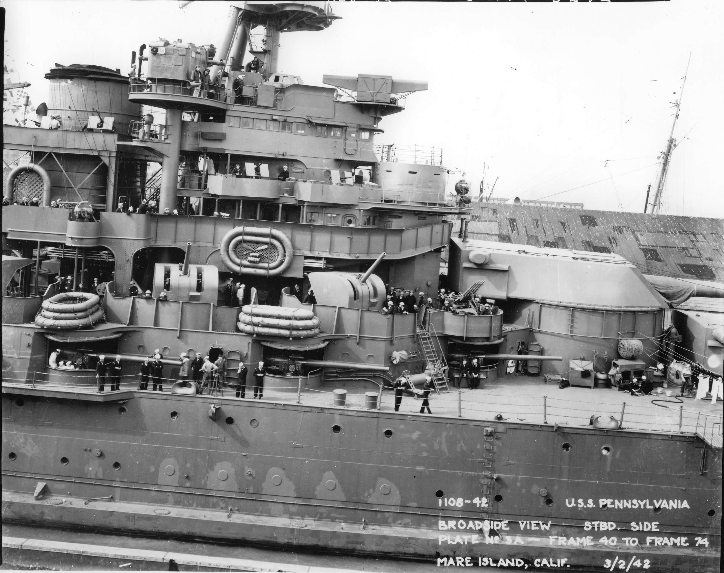
Yes, I used those drawings to calculate the scale length of the two guns. I also used the following picture of Pennsylvania to measure how much the 5"/51 barrel should stick out from the casemate:
http://navsource.org/archives/01/038/013803c.jpg
Mike
Yes, I used those drawings to calculate the scale length of the two guns. I also used the following picture of Pennsylvania to measure how much the 5"/51 barrel should stick out from the casemate:
http://navsource.org/archives/01/038/013803c.jpg
Mike
-
FFG-7
- Posts: 698
- Joined: Wed Mar 13, 2024 9:45 am
Re: Battleship Row in 1/700
Arizona's Booklet of General Plans I linked on pg 2 of this thread would have done the same thing.
-
mconnelley
- Posts: 249
- Joined: Sun Feb 07, 2010 8:13 pm
Re: Battleship Row in 1/700
Here's a test install of the first casemate gun. From the green resin you can tell that this is Arizona.
The key to this install is that the gun is glued to the 'ceiling' of the casemate. I did it this way because:
1) If they were glued to the main deck, I couldn't install the superstructure deck because the lower 'wall' of the casemate would hit the gun barrel. I can't install the gun afterwards because the opening in the casemate isn't large enough for the gun to pass through
2) It allows me to position the gun correctly relative to the casemate, instead of relative to the main deck.
Photos (like the one linked above) show that the gap above the gun is a bit larger than the gap below. I glued a 0.5 mm shim above the gun to set its height correctly. I measured the depth of the casemate 'pocket' (in this case, 2.2 mm), and filed down the base of the gun so that its overall height (with the shim) to 2.2 mm. Having done this, when the superstructure deck is placed onto the main deck, the base of the gun will also be on the main deck. I positioned the gun so that 4 mm of the barrel sticks out. I used white glue so that I'd have time to adjust the position of the gun.
One down. 69 to go...
- Attachments
-
-
Dan K
- Posts: 9042
- Joined: Tue Jan 11, 2005 10:56 am
- Location: New York City
-
mconnelley
- Posts: 249
- Joined: Sun Feb 07, 2010 8:13 pm
Re: Battleship Row in 1/700
Hello:
Work on the battleships has been slower lately due to distractions from other projects (specifically a 1/32 F-14 and the Yamashiro in 1/350). But I have gotten all of the 5" casemates installed for Arizona and Oklahoma. Here's what it looks like in Arizona. I've made a few of the guns elevated a bit just to add a little more visual interest.
The last photo shows what it looks like from below. I measured the depth of each pocket with a caliper, and wrote it on the part. I then filed each gun to that height. So, although the guns are glued to the overhead, the base will sit on the deck or at least very close to it.
Mike
- Attachments
-
-
-
-
mconnelley
- Posts: 249
- Joined: Sun Feb 07, 2010 8:13 pm
Re: Battleship Row in 1/700
I decided to scratch build the 'bird bath' machine gun platform on Nevada. Whereas the bird bath is mounted at a 45 degree angle to the long axis of the ship on Oklahoma and Arizona, it was mounted square to the long axis of the ship on Nevada. The kit bird bath is a bit out of square, and is a bit of a parallelogram. On Oklahoma, where it's mounted at an angle, this is harder to see, but it's more obvious on Nevada.
In the photo, the new bird bath is mounted on the main mast, and I'm holding the kit resin part in the tweezers.
And just for a bit of eye candy, here are the three ships in their current state.
Mike
In the photo, the new bird bath is mounted on the main mast, and I'm holding the kit resin part in the tweezers.
And just for a bit of eye candy, here are the three ships in their current state.
Mike
- Attachments
-
-