marijn van gils wrote:I guess you are using one of these?
1/400 SLC Maiale manned torpedo
Moderators: BB62vet, MartinJQuinn, JIM BAUMANN, Jon, Dan K
-
SG1
- Posts: 402
- Joined: Mon Apr 17, 2017 2:43 am
- Contact:
Re: 1/400 SLC Maiale manned torpedo
-
SG1
- Posts: 402
- Joined: Mon Apr 17, 2017 2:43 am
- Contact:
Re: 1/400 SLC Maiale manned torpedo
Hi, I thought there might be room for improvement and decided to push myself to the limits. I drilled another hole for the depth gauge (a) and filled it with a 0.13 mm-thin section of 0.3mm brass rod; I "punched" 4 x 0.1 mm aluminium foil "dots" with a homemade micro p&d (don't try this at home, it seldom works  ) and glued the dots to represent the ammeters and voltmeters on the right of the panel (b): the dots kept disappearing among the bristles of the carrier-brush and aligning the few of them that made it to the cluster was a pure statistical exercise . Finally, i tried to smooth out the corners of the frame sanding it gently with 2000 grit sandpaper to avoid disassembling the frame elements (c). The result is more pleasing to the naked eye than seen through the merciless camera magnification. Trying to capture all the new elements in a picture was difficult due to the different reflections of every single detail.
The idea is to provide some extra texture to be enhanced with drybrush over the black instrument panel, before creating the glass over it. Theoretically it should improve detailing. We'll see. Something i won't be repeating anytime soon by the way
Cheers,
SG
The idea is to provide some extra texture to be enhanced with drybrush over the black instrument panel, before creating the glass over it. Theoretically it should improve detailing. We'll see. Something i won't be repeating anytime soon by the way
Cheers,
SG
- Attachments
-
Last edited by SG1 on Mon Nov 03, 2025 6:22 am, edited 1 time in total.
-
SG1
- Posts: 402
- Joined: Mon Apr 17, 2017 2:43 am
- Contact:
Re: 1/400 SLC Maiale manned torpedo
Hello,
added the controls for the trim pumps to the instrument cluster (several styles existed, a, b, c). Opted for a single subassembly to spare myself from the difficulty of gluing the single components to the SLC at a later stage, when the surface of the torpedo will be filled with details. There should be room for a better alignment of the controls using controlled "pin washes" of CA debonder i hope. Placing a single subassemblied element instead of three should make it easier.
Each cylindrical horizontal part is composed of two tiny sections of 0.2 mm brass tubing mounted on a 0.1mm rod section. Overall lenght of the combos is 0.3 mm. I left in place the burr that formed-up at the edges after diamond-filing the sections of tubing to simulate the raised connection-rim between the components of the real thing (e).
Each horizontal part was glued to the corresponding vertical element, made of a 0.17ish mm wide x 0.2 mm tall tubing section hosting a trim pump lever made with 0.046mm wire that has a knob on top.
Obtaining the 0.17mm-wide tubing sections was a laborious affair, basically the brass tube is rolled over the surface of a CD with a diamond file checking width reduction time by time, stopping before the tube breaking point is reached.
The knobs on top of the levers are micro blobs of white glue applied with the tip of a 5/0 brush. I used "The Baumann Technique" of mixing white glue and watercolour, in this case black. It is a very effective technique to control the apposition of the micro blob of glue and the build-up of the knobs, making them visible after the glue has cured. THANK YOU MR BAUMANN, this is an official tribute.
I prepared a "forest" of levers with different heights ranging from 0.5 to 0.8 mm and chose the most appropriate ones according to the pictures of the real thing (f).
Gluing the controls to the instrument cluster was a matter of trial and error. I prepared a jig to help adapting the controls to the curved surface of the torpedo. The weak point of my work was the choice of 0.1 x 0.1mm wire for the spacers (d). The minimal contact surface was very difficult to control when gluing the parts. Am happy of the result, although i think there's still room for improvement. I am tempted to undo the work and go for squared/thinner spacers made of self-adhesive aluminium tape to simulate version (c) thinner spacers. We'll see. The complete subassembly is really small, as i discovered when i tried to man the levers with my index finger. Enjoy the result of my work.
Cheers,
SG
added the controls for the trim pumps to the instrument cluster (several styles existed, a, b, c). Opted for a single subassembly to spare myself from the difficulty of gluing the single components to the SLC at a later stage, when the surface of the torpedo will be filled with details. There should be room for a better alignment of the controls using controlled "pin washes" of CA debonder i hope. Placing a single subassemblied element instead of three should make it easier.
Each cylindrical horizontal part is composed of two tiny sections of 0.2 mm brass tubing mounted on a 0.1mm rod section. Overall lenght of the combos is 0.3 mm. I left in place the burr that formed-up at the edges after diamond-filing the sections of tubing to simulate the raised connection-rim between the components of the real thing (e).
Each horizontal part was glued to the corresponding vertical element, made of a 0.17ish mm wide x 0.2 mm tall tubing section hosting a trim pump lever made with 0.046mm wire that has a knob on top.
Obtaining the 0.17mm-wide tubing sections was a laborious affair, basically the brass tube is rolled over the surface of a CD with a diamond file checking width reduction time by time, stopping before the tube breaking point is reached.
The knobs on top of the levers are micro blobs of white glue applied with the tip of a 5/0 brush. I used "The Baumann Technique" of mixing white glue and watercolour, in this case black. It is a very effective technique to control the apposition of the micro blob of glue and the build-up of the knobs, making them visible after the glue has cured. THANK YOU MR BAUMANN, this is an official tribute.
I prepared a "forest" of levers with different heights ranging from 0.5 to 0.8 mm and chose the most appropriate ones according to the pictures of the real thing (f).
Gluing the controls to the instrument cluster was a matter of trial and error. I prepared a jig to help adapting the controls to the curved surface of the torpedo. The weak point of my work was the choice of 0.1 x 0.1mm wire for the spacers (d). The minimal contact surface was very difficult to control when gluing the parts. Am happy of the result, although i think there's still room for improvement. I am tempted to undo the work and go for squared/thinner spacers made of self-adhesive aluminium tape to simulate version (c) thinner spacers. We'll see. The complete subassembly is really small, as i discovered when i tried to man the levers with my index finger
Cheers,
SG
- Attachments
-
-
-
Last edited by SG1 on Fri Apr 12, 2024 3:10 am, edited 9 times in total.
-
Vladi

- Posts: 809
- Joined: Mon Feb 21, 2011 6:38 am
- Location: Czech Republic
- Contact:
Re: 1/400 SLC Maiale manned torpedo
Very nice (and crazy  ) indeed!
Battle of Savo Island Collection (all 1/700)
Recently completed: HMAS Australia | USS Patterson DD-392
At works: USS Astoria CA-34
Prep stage: USS Vincennes CA-44 | Yubari | Kako
Recently completed: HMAS Australia | USS Patterson DD-392
At works: USS Astoria CA-34
Prep stage: USS Vincennes CA-44 | Yubari | Kako
-
marijn van gils
- Posts: 2686
- Joined: Tue Feb 06, 2007 10:24 am
- Location: Belgium
Re: 1/400 SLC Maiale manned torpedo
Fantastic!
When this is ready, ants will be able to actually work this torpedo!
I'm looking forward to that spiders' nest of tubes
When this is ready, ants will be able to actually work this torpedo!
I'm looking forward to that spiders' nest of tubes
-
SG1
- Posts: 402
- Joined: Mon Apr 17, 2017 2:43 am
- Contact:
Re: 1/400 SLC Maiale manned torpedo
Thank you, Vladi and Marijn!
That will be fun to do . Am still not convinced it's feasible, plus bending to that crazy shape the 0.06 mm wire needed for the job will be a real issue. Just thinking of it gives me the shivers Thank god the tail section comes first. I hope to start working on it soon! 
marijn van gils wrote: I'm looking forward to that spiders' nest of tubes
That will be fun to do
-
EJFoeth
- Posts: 2909
- Joined: Wed Jan 21, 2009 1:51 pm
Re: 1/400 SLC Maiale manned torpedo
Great work Stefano! And I wonder, with this level of detail, will she ever be finished? 
-
SG1
- Posts: 402
- Joined: Mon Apr 17, 2017 2:43 am
- Contact:
Re: 1/400 SLC Maiale manned torpedo
Hehehehe EJ, she will. Sooner or later she will be finished, more likely later that sooner. Time is not the issue here, as you very well know. Am not in a hurry
Thanks for the support
Thanks for the support
-
SG1
- Posts: 402
- Joined: Mon Apr 17, 2017 2:43 am
- Contact:
Re: 1/400 SLC Maiale manned torpedo
Hi! made some (meagre) progress with the tail section: scribed the demarcation lines for the propeller guard (a) and propeller (b) plus drilled the three holes to host the propeller blades (c).
Scribing a curvy surface this small proved to be a tough nut to crack. Finding a valid guide/support for the scribing needle was the main problem: tried with different types of masking tape (low-tack, velvety rubbery ultrathin): didn't work. Tried with tiny strips of decals too: didn't work either. Both the tape and the decals were too stiff as not to adapt/adhere to the tiny contact surface of the SLC tail cone (the last 0.3-0.5 mm of it). The solution came from the marvellous set of PE'd ultrafine circles from the Shelf Oddity range I had in my stash. Jolly good product. An appropriate circle (d) was selected, fitted and temporarily glued to the SLC tail cone with a droplet of CA. Demarcation line was scribed easily, then the circle was removed with CA-debonder. Refinement with sandpaper followed. Process was repeated for the wider line (a).
The holes meant to host the propeller blades had to be drilled with angle of 120 degrees separating the three of them. (e) I prepared a paper Jig that was punched in the middle with a p&d to adapt to the propeller section. Holes were marked following the jig's direction, with a pointy pencil tip first, then with a needle, drilled out with a 0.1mm drillbit and subsequently enlarged to 0.15mm. Job done.
now the rest of it!
Cheers,
SG
Scribing a curvy surface this small proved to be a tough nut to crack. Finding a valid guide/support for the scribing needle was the main problem: tried with different types of masking tape (low-tack, velvety
The holes meant to host the propeller blades had to be drilled with angle of 120 degrees separating the three of them. (e) I prepared a paper Jig that was punched in the middle with a p&d to adapt to the propeller section. Holes were marked following the jig's direction, with a pointy pencil tip first, then with a needle, drilled out with a 0.1mm drillbit and subsequently enlarged to 0.15mm. Job done.
now the rest of it!
Cheers,
SG
- Attachments
-
Last edited by SG1 on Mon Nov 03, 2025 5:55 am, edited 1 time in total.
-
SG1
- Posts: 402
- Joined: Mon Apr 17, 2017 2:43 am
- Contact:
Re: 1/400 SLC Maiale manned torpedo
Hi, have finally crafted 3 sister-blades from 0.02mm brass shim
Cheers,
SG
Cheers,
SG
- Attachments
-
-
wefalck

- Posts: 2082
- Joined: Wed Sep 28, 2011 12:04 pm
- Location: Paris
- Contact:
Re: 1/400 SLC Maiale manned torpedo
Don't breath
Eberhard
Former chairman Arbeitskreis historischer Schiffbau e.V. (German Association for Shipbuilding History)
--------------------------------------------------------------------------------------------------------------------------------------------------------------------------------------------


Former chairman Arbeitskreis historischer Schiffbau e.V. (German Association for Shipbuilding History)
--------------------------------------------------------------------------------------------------------------------------------------------------------------------------------------------
-
SG1
- Posts: 402
- Joined: Mon Apr 17, 2017 2:43 am
- Contact:
-
EJFoeth
- Posts: 2909
- Joined: Wed Jan 21, 2009 1:51 pm
Re: 1/400 SLC Maiale manned torpedo
Fortunately only three blades; hope they don�t fall during glueing 
-
dafi

- Posts: 998
- Joined: Mon Mar 12, 2012 11:13 am
- Location: Ludwigsburg/Germany
- Contact:
Re: 1/400 SLC Maiale manned torpedo
Haven�t seen this topic yet ...
... it was apparently to small for my eyesight
We will have to hold our breaths, until the end ...
XXXDAn
... it was apparently to small for my eyesight
We will have to hold our breaths, until the end ...
XXXDAn
To Victory and beyond ...
viewtopic.php?f=59&t=99050&start=60
See also our german forum for the age of Sail and History:
http://www.segelschiffsmodellbau.com
viewtopic.php?f=59&t=99050&start=60
See also our german forum for the age of Sail and History:
http://www.segelschiffsmodellbau.com
-
dafi
- Posts: 998
- Joined: Mon Mar 12, 2012 11:13 am
- Location: Ludwigsburg/Germany
- Contact:
Re: 1/400 SLC Maiale manned torpedo
PS: The valves: They work I suppose?
XXXDAn
XXXDAn
To Victory and beyond ...
viewtopic.php?f=59&t=99050&start=60
See also our german forum for the age of Sail and History:
http://www.segelschiffsmodellbau.com
viewtopic.php?f=59&t=99050&start=60
See also our german forum for the age of Sail and History:
http://www.segelschiffsmodellbau.com
-
SG1
- Posts: 402
- Joined: Mon Apr 17, 2017 2:43 am
- Contact:
Re: 1/400 SLC Maiale manned torpedo
of course they do!dafi wrote:PS: The valves: They work I suppose?
Quick update: experiencing a lot of trouble with the warhead tip these days, due to an amateur-ish clumsy miscalculation of lenght of a brass rod section that had to be added into a pre-drilled hole to protrude only a few tenths of a mm. The section gone buried into the hole and the consequent dug out left a messy tip to say the laest.
Trying to solve the problem and save the countless-hour work already done on the warhead through redrilling hole(s), filling it (them) with styrene rod(s) and reshaping a previously almost perfect tip. This will take time and postpone work on the tail section. One step forward, two steps back, classic. Dreadful days these days
-
EJFoeth
- Posts: 2909
- Joined: Wed Jan 21, 2009 1:51 pm
Re: 1/400 SLC Maiale manned torpedo
Ouch, sounds like my own experience with drills breaking and remaining stuck in the model� Now, if the goal was to have a tiny bit of the rod protruding, you could try making it a bit too long, take a plastic strip of the right thickness and a small hole, add it to the pin as a sanding stop? Use that trick a lot for tube and rod to have a given height accurately�? E.g:
-
SG1
- Posts: 402
- Joined: Mon Apr 17, 2017 2:43 am
- Contact:
Re: 1/400 SLC Maiale manned torpedo
had thought of that EJ, but the only 0.05mm-thick spacer available would have been brass shim, which i judged wrongly to be too difficult to perforate, and then reaching an even/not oblique alignement of the jig on the very small tip of the warhead would have exposed me to the problem that eventually happened following another wrong decision.EJFoeth wrote:Now, if the goal was to have a tiny bit of the rod protruding, you could try making it a bit too long, take a plastic strip of the right thickness and a small hole, add it to the pin as a sanding stop? Use that trick a lot for tube and rod to have a given height accurately�?
Had also thought to add some extra-spacing to overcome the mistake, but then i imagined that crafting a 0.05-ish thick brass dot of 0.2 mm diameter and glueing it perfectly on the spot would be too painful. So i took the wrong decision to go for the dug-out. Typical
Take-home messages for the future. Thanks for the tip anyway, very much appreciated
-
EJFoeth
- Posts: 2909
- Joined: Wed Jan 21, 2009 1:51 pm
Re: 1/400 SLC Maiale manned torpedo
Figured you already considered that. So this rod was not inserted in a tube but directly into the styrene? In any case, too late now, you could have puttied it all over and add the tip by a very small dot of paint, a tad lighter than the surrounding layer� you probably want to highlight these details anyway�
-
SG1
- Posts: 402
- Joined: Mon Apr 17, 2017 2:43 am
- Contact:
Re: 1/400 SLC Maiale manned torpedo
Hi, it's been a while, here's what happened:
situation at the end of october was pretty desperate. Attempts to superdetail the tip of the warhead had led to serious damage that needed filling and reshaping (a) (twice ). Manipulation caused the SLC to break in two at the after nut ring (b) that acted as a line of least resistance along which the breaking occurred. I was on the verge of quitting the project but then stubbornness prevailed. I glued the two sections with liquid cement and filled the resulting damage with epoxy putty, then filled and reshaped the warhead tip for the third time.
Study of Royal Navy declassified files revealed the existence of two oblique plain primers at the bottom surface of the warhead (d). Since the information was completely new to me (couldn't find images anywhere to confirm the finding, all the scale model kits on the market are lacking the detail) i decided to visit the Historical Naval Museum in Venice (that hosts a wartime/late series SLC) to verify the finding.
Careful examination of the SLC undersides confirmed the presence of the oblique plain primers and also revealed the existence of a welding line running all along the bottom midline of the SLC main body, sparing the warhead. It looked suprisingly prominent (e). The discovery really made my day! (c)
Once back at home i decided to superdetail the warhead of my SLC model according to the new findings and to craft a new quick release gear.
- Two 0.2 mm oblique holes were drilled on the bottom midline of the warhead, then drilled 0.1 holes deep in the 0.2mm tunnels and added tiny sections of 0.1 wire to simulate the plain primers (d).
- The welding line was simulated by glueing a 0.01 mm copper wire section all along the bottom midline of the SLC body (e). I used a 0.02mm copper wire applicator to run ultrathin CA along the joint and sanded the weld line with 2000-grit sandpaper to reduce bulking which i must say is nearly imperceptible.
- Drilled another nut ring further aft of the breaking line (f) and added the band at the warhead demarcation line, made of 0.03 mm copper wire (g).
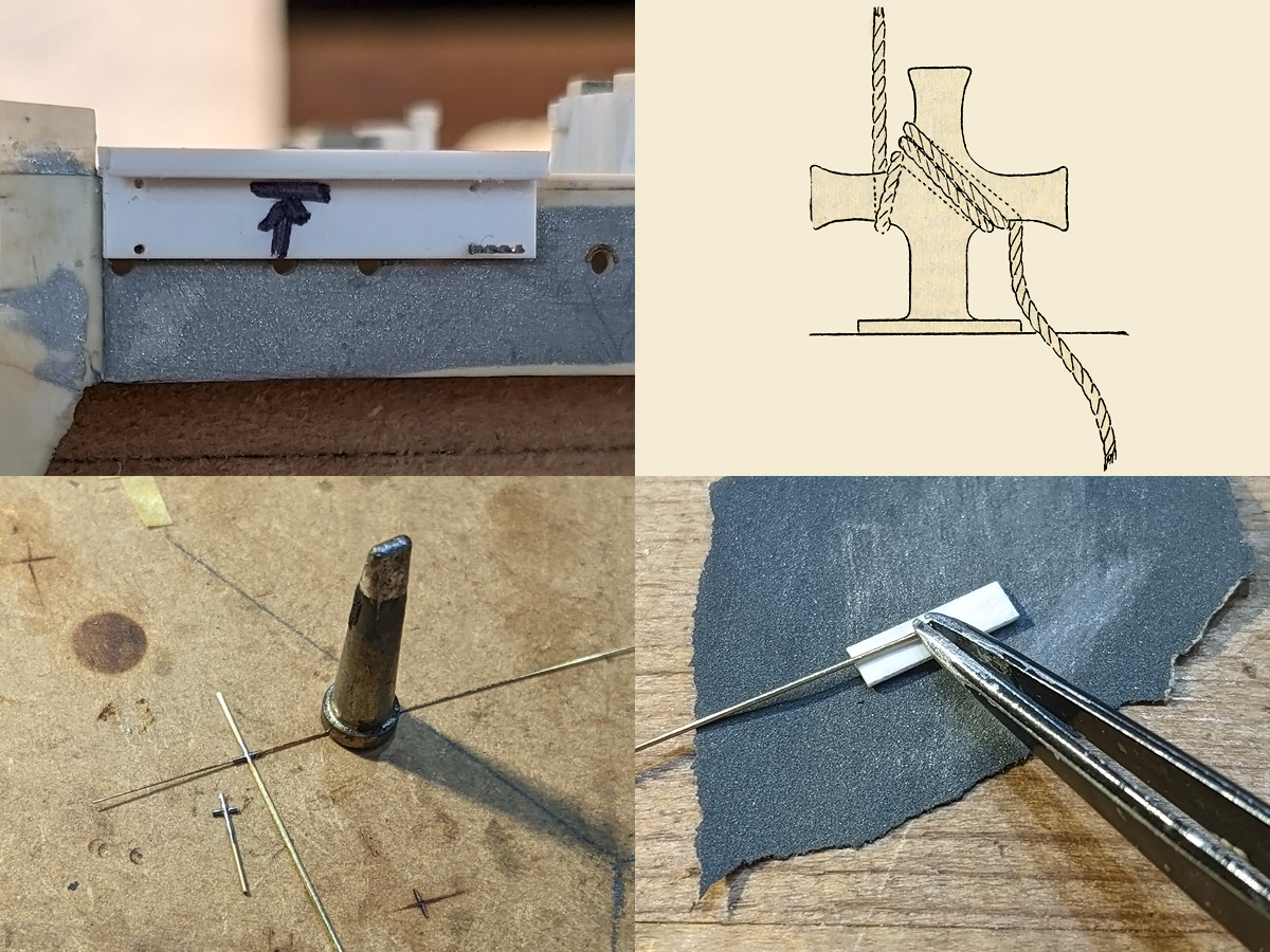
- Finally crafted a new version of the quick release gear (h) with a section of 0.2 mm brass rod protruding the right amount this time ( ) and a tiny strip of 0.01 mm-thin brass shim (measuring 0.7x 0.05 mm) which was very difficult to craft, align and glue.
Cheers,
SG
situation at the end of october was pretty desperate. Attempts to superdetail the tip of the warhead had led to serious damage that needed filling and reshaping (a) (twice
Study of Royal Navy declassified files revealed the existence of two oblique plain primers at the bottom surface of the warhead (d). Since the information was completely new to me (couldn't find images anywhere to confirm the finding, all the scale model kits on the market are lacking the detail) i decided to visit the Historical Naval Museum in Venice (that hosts a wartime/late series SLC) to verify the finding.
Careful examination of the SLC undersides confirmed the presence of the oblique plain primers and also revealed the existence of a welding line running all along the bottom midline of the SLC main body, sparing the warhead. It looked suprisingly prominent (e). The discovery really made my day! (c)
Once back at home i decided to superdetail the warhead of my SLC model according to the new findings and to craft a new quick release gear.
- Two 0.2 mm oblique holes were drilled on the bottom midline of the warhead, then drilled 0.1 holes deep in the 0.2mm tunnels and added tiny sections of 0.1 wire to simulate the plain primers (d).
- The welding line was simulated by glueing a 0.01 mm copper wire section all along the bottom midline of the SLC body (e). I used a 0.02mm copper wire applicator to run ultrathin CA along the joint and sanded the weld line with 2000-grit sandpaper to reduce bulking which i must say is nearly imperceptible.
- Drilled another nut ring further aft of the breaking line (f) and added the band at the warhead demarcation line, made of 0.03 mm copper wire (g).
- Finally crafted a new version of the quick release gear (h) with a section of 0.2 mm brass rod protruding the right amount this time (
Cheers,
SG
- Attachments
-
-
-
Last edited by SG1 on Sat Dec 27, 2025 5:33 am, edited 1 time in total.