Got both some good and some bad news.
The good news is I went out to sail with Well Enhancer, and despite the high waves (scale 8-9 Beaufort) the stern remained completely dry this time.
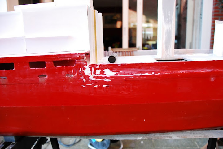
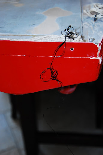
Than the bad news, I found a crack in the bow just below the waterline.
I found this crack after some 15-20 minutes of sailing, and there did get water inside, which hasn't happened in similar situations before.
I'm hoping to get this fixed before 30 April, as I'm then taking her with me to the model boating club for queens day.
Has anyone some advice how I could permanently fix this crack?
I'm hoping there'll be some way which doesn't require fibre glassing or anything like that big a job...
Could epoxy glue do the job?
Enough talking, now some photo's:

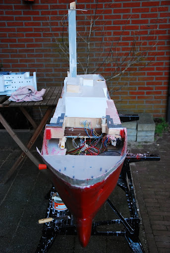
Moored and waiting for ballast.
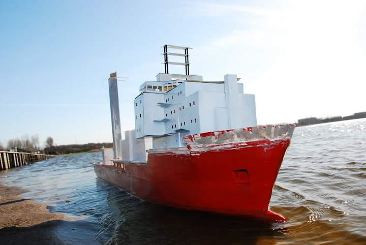
Ballast placed, moored for some photographing with the bulwark still in 1 piece...

Found a beach not far from the car, which was nicely covered from the wind, making it easier to get going.
In the rear of this photo the higher waves on the open part of the water are visible.

It took me a while to get going properly (one needs to be gentle with the rudder when using azimuths in weather like this), but as soon as I found out how to work a way through it I got her sailing against the wind for some time.
With the wind in the side of the model gave a somewhat scary sight, which will be shown in some photo's further down this post.


Ballast was really properly spread out, it's the waves and the wind causing her get some list...

Nicely high waves, this is one of the reasons why I like these kind of ships.
The engines didn't like it as much as I did, I noticed they refused to go to full power from time to time.
This makes me consider adding temperature gauges and Amp meters so I can see when they're getting hot.
It also makes me consider to use Speed 700 Toque engines on Seven Atlantic rather then the less powerful Speed 500 E's of Well Enhancer, though Seven Atlantics 5-bladed brass props might give more power already, and Seven Atlantic has 3 azimuths under the stern compared to just 2 in Well Enhancer.

When sailing takes as much attention as did today, taking proper photo's using a DSLR isn't quite easy.
As a result of that this shot is out of focus...


This is how I managed to get some proper photo's whilst controlling the model (well, at least sort of controlling...).

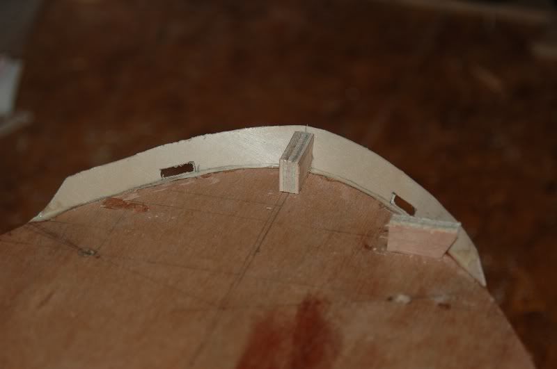
The damage to the bow.
I think this crack is about 5cm long.
When something like this gets stuck around a prop the performance won't be what one would expect it to be...
Greetings Josse
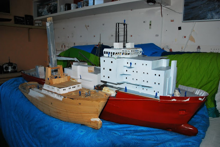
Making a complete new Well Enhancer, again scale 1:75.